12 Programmable Relay ZEN
Nomenclature
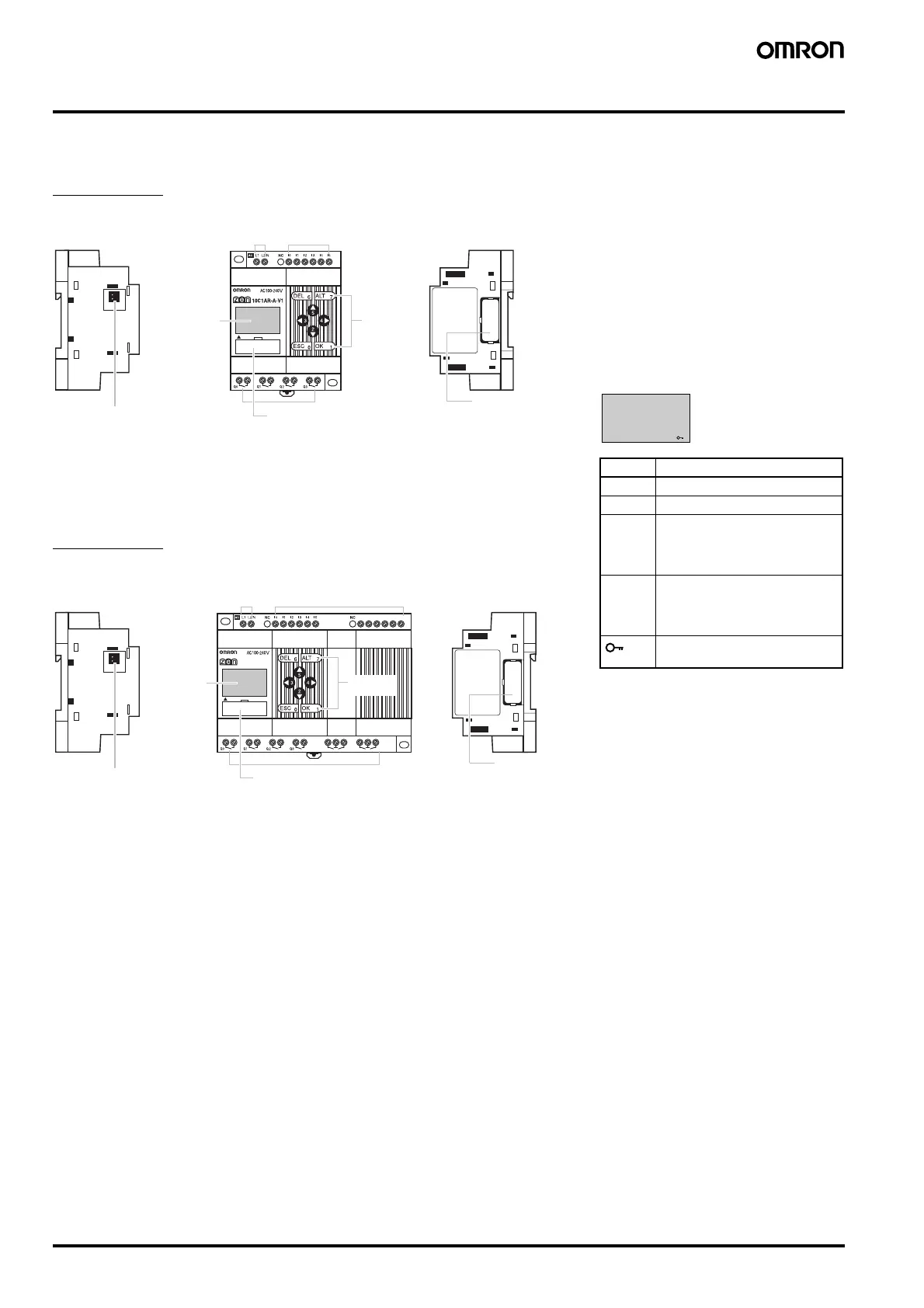
■ LCD type
10 I/O Units
20 I/O Units
Note:
1
See page 9 for Specifiactios Buttons Input Bits
Left Side
Battery Unit connector
(Remove the seal to
connect the Battery Unit.)
Front
Power supply
terminals
Input terminals
LCD Operation
buttons
1
Output terminals
ZEN Support Software connector
(also used for Memory Cassette.)
Right Side
Expansion Unit
connector cover.
Remove this cover to
connect Expansion Unit.
ZEN Support Software connector
(also used for Memory Cassette.) Remove this cover to
connect Expansion Unit.
Q
4
I
6
I
7
I
8
I
9
I
a
I
b
Q
6
Q
5
Q
7
20C1AR-A-V1
Left Side
Battery Unit connector
(Remove the seal to
connect the Battery Unit.)
F
r
o
n
t
Power supply
terminals
Input terminals
LCD
Operation
buttons
1
Output terminals
Right Side
Expansion Unit
connector cover.
ZEN Support Software connector
(also used for Memory Cassette.)
Remove this cover to
connect Expansion Unit.
Icon Meanings
Icon Meaning
RUN Displayed while in RUN mode.
ERR Indicates an error.
▲ Displayed when there is a
higher-level menu or ladder pro-
gram line than the one currently
displayed.
▼ Displayed when there is a lower-
level menu or ladder program
line than the one currently dis-
played.
Displayed when a password has
been set.
RUN ERR
▲ ▼
AUDIN - 8, avenue de la malle - 51370 Saint Brice Courcelles - Tel : 03.26.04.20.21 - Fax : 03.26.04.28.20 - Web : http: www.audin.fr - Email : info@audin.fr