8 Programmable Relay ZEN
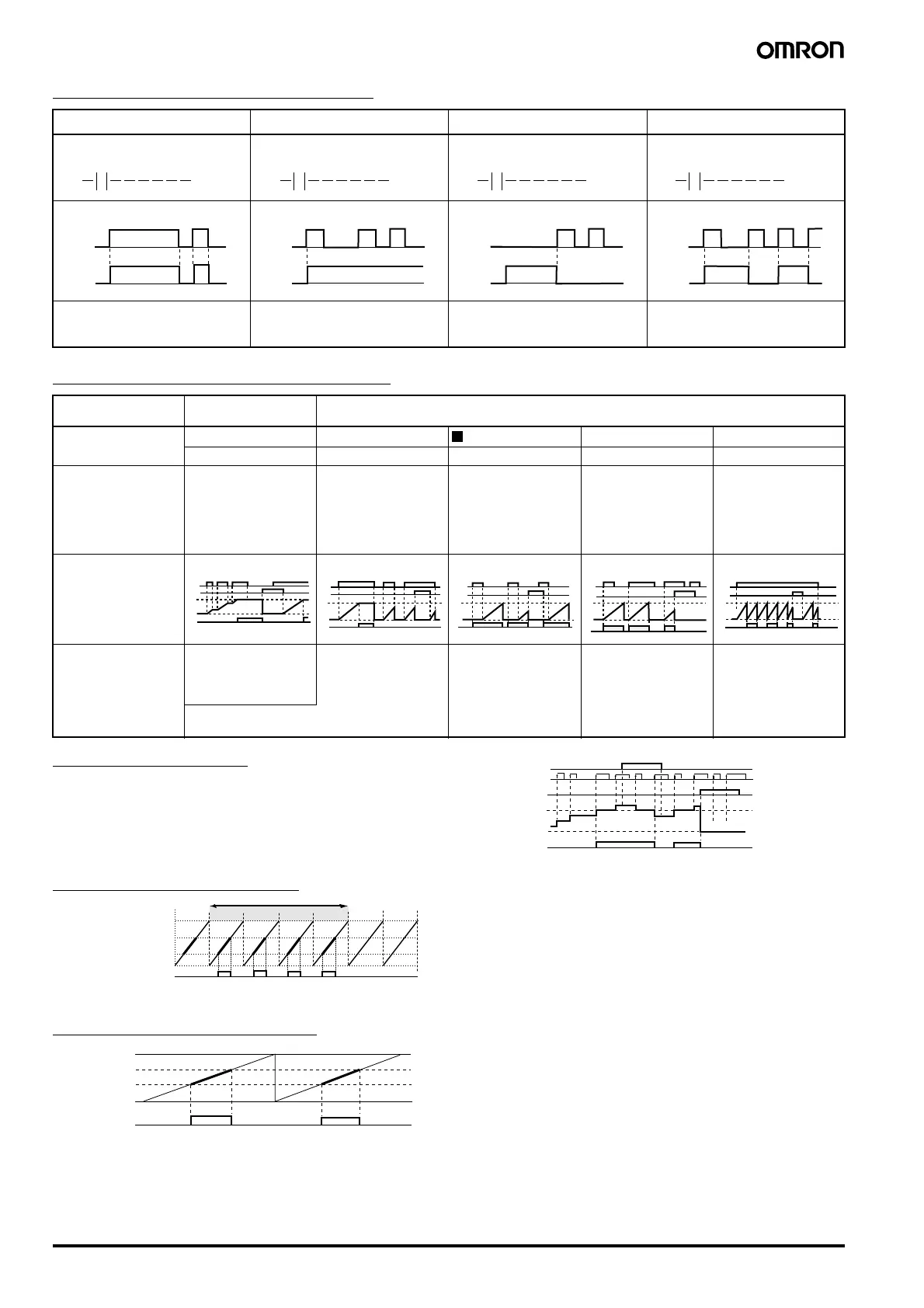
1 Additional Bit Output Functions
2 Using Timers and Holding Timers
3 Counter Operation
The counter bit turns ON when the counter value (present value)
reaches the set value (present value ≥ set value). The count returns
to 0 and the counter bit turns OFF when the reset input turns ON.
Count inputs are not accepted while the reset input is turned ON.
The counter present value and counter bit (ON/OFF) are held even if
the operating mode is changed or the power supply is interrupted
.
4 Weekly Timer Operation
5 Calendar Timer Operation
[: Normal S: Set R: Reset
A: Alternate
Q0 will turn ON or OFF depending
on the ON/OFF status of the
execution condition I0.
Q1 will stay ON once the execution
condition I1 has turned ON once.
A reset is used to turn Q1 OFF.
Q1 is forced OFF when the
execution condition I2 is turned
ON.
Q2 alternates between turning
ON and OFF when the execution
condition I3 turns ON.
Available timers Holding timers
(#0 to #7)
Timers (T0 to Tf)
Timer type X X O F
ON-delay timer only ON-delay timer OFF-delay timer One-shot pulse timer Flashing pulse timer
Operation Turns ON after set
delay after the trigger
input turns ON.
Turns ON after set
delay after the trigger
input turns ON.
Stays ON while the
trigger input is ON and
turns OFF after a set
delay after the trigger
input has turned OFF.
Turns ON for a set
period after the trigger
input turns ON and
regardless of how
long the trigger input
remains ON.
Repeatedly turns ON
and OFF in a set cycle
while the switch is ON.
Trigger input
Reset input
Setting
Present value
Timer input condition
Main applications To continue operation
after momentary
power loss or power
interruptions.
Useful for OFF delay
circuits for lights or
fans.
Useful for set
operations where
operation is always
required during a
regular period only.
Useful for flashing
emergency lights or
sounding buzzers as
the output for an alarm
circuit.
When delayed operation or a time lag is
required.
I0
[ Q 0
I1
SQ 1
I2
RQ 1
I3
AQ 2
I0
Q0
I1
Q1
I2
Q1
I3
Q2
0
0
0
0
0
I0(DIR)
I1(CNT)
I2(RES)
Setting
Present value
0000
Counter C0 bit
24:00
Stop time 17:30
Start time 8:15
00:00
Weekly timer @0 input condition
Date setting
Time setting
Input condition @0 turns ON between 8:15 and 17:30, Tuesday to Friday every week.
Mon Tues Wed Thurs Fri Sat Sun
Dec 31
Sep 1
Apr 1
Jan 1
Calendar timer
*0 bit
Start date
Bit *0 turns ON between April 1 and August 31.
Stop date
AUDIN - 8, avenue de la malle - 51370 Saint Brice Courcelles - Tel : 03.26.04.20.21 - Fax : 03.26.04.28.20 - Web : http: www.audin.fr - Email : info@audin.fr