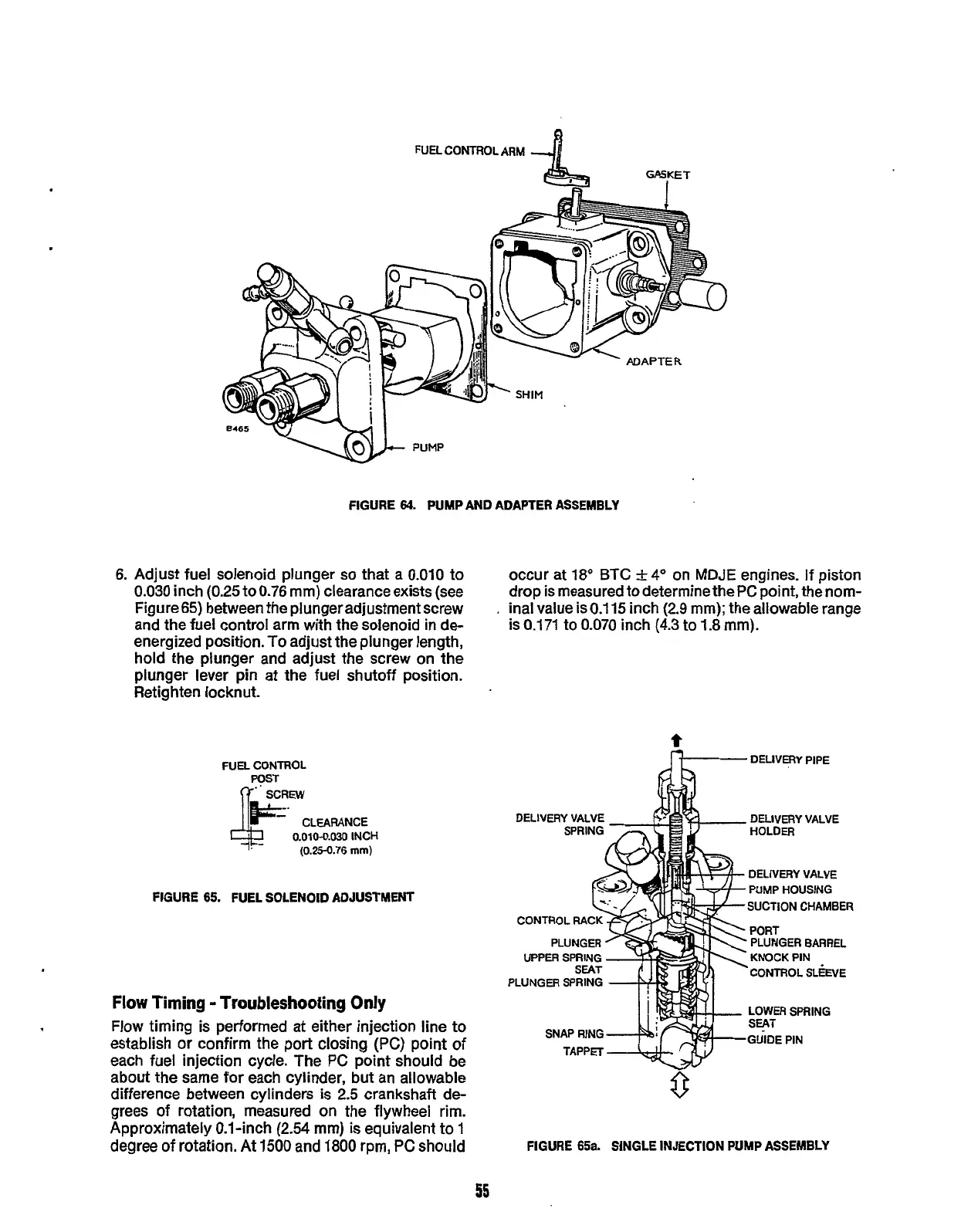
FIGURE
64.
PUMP AND ADAPTER
ASSEMBLY
6.
Adjust fuel solenoid plunger
so
that a
0.010
to
0.030
inch
(0.25
to 0.76 mm) clearance exists (see
Figure65) between the plunger adjustment screw
and the fuel control arm with the solenoid
in
de-
energized position.
To
adjust the plunger length,
hold the plunger and adjust the screw on the
plunger lever pin at the fuel shutoff position.
Retighten locknut.
occur at 18"
BTC
+4"
on
MDJE
engines. If piston
drop is measured to determine the PC point, the nom-
.
inal value is
0.1
15
inch (2.9 mm); the allowable range
is 0.171 to 0.070 inch
(4.3
to 1.8 mm).
FUEL
CONTROL
CLEARANCE
0.010-0.030
INCH
(0.25-0.76
mm)
FIGURE
65.
FUEL SOLENOID ADJUSTYEW
Flow
Timing
-
Troubleshooting Only
Flow timing is performed at either injection line to
establish
or
confirm the port closing (PC) point
of
each fuel injection cycle. The PC point should be
about
the
same for each cylinder, but an allowable
difference between cylinders is
2.5
crankshaft
de-
grees of rotation, measured
on
the flywheel rim.
Approximately 0.1-inch
(2.54
mm)
is
equivalent to
1
degree
of
rotation.
At
1500
and
1800
rpm, PC should
t
DELIVERY
PIPE
DELIVERY VALVE
DELIVERY
VALVE
HOLDER
DELIVERY
VALVE
PUMP
HOUSING
SUCTION
CHAMBER
PORT
PLUNGER BARREL
KNOCK
PIN
UPPER
SPRING
PLUNGER
SPRING
CONTROL
SL&E
LOWER
SPRING
SEAT
GUIDE
PIN
FIGURE
65a.
SINGLE INJECTION PUMP ASSEMBLY
55
Redistribution or publication of this document,
by any means, is strictly prohibited.