Flow
Timing Procedure
To
determine PC, proceed as follows:
1.
Remove one high pressure line (both ends), and
the corresponding delivery valve holder, spring,
volume reducer, and delivery valve, Figure 65a.
Leave gasket and seat in pump.
Place the spring and volume reducer in a clean container
of
fuel until re-installed.
2. Re-install delivery valve holder (without spring
and volume reducer).
3.
Install high pressure line
on
delivery valve outlet
so
that drops of fuel can be easily counted and
collected in a receptacle at the open end
of
the
line.
4.
Move the fuel control arm toward the front of the
engine to full fuel range.
The fuel solenoid must be energized or held (blocked) to keep
the plunger
out
of the way.
5.
Manually operate transfer pump lever to provide
fuel pressure to injection pump.
6. Rotate flywheel clockwise very slowly by hand
until fuel stops flowing from open line, even
though transfer pump operation is continued.
7. Rotate flywheel counterclockwise until fuel flows
freely; then, clockwise very slowly to position
where fuel drops can be counted at one drop per
second with the transfer pump operating.
This is the PC point;
it
should be marked on the flywheel
opposite the timing pointer.
8.
After flow timing iscompleted, remove high pres-
sure line and delivery valve holder; then, reinstall
delivery valve, spring, and volume reducer.
Make sure all parts are
clean.
9. Reinstall delivery valve holder and torque Bryce
holder to 29 to 33 ft.-lb. (39 to
44 Nm). Torque
Kiki holder to
44
to 47 ft.-lb.
(60-64
Nm). If fuel
leakage occurs, replace the delivery valve gasket.
10.
Reinstall high pressure line between pump and
nozzle.
11.
Using the same procedure, flow timing can be
performed on the other cylinder to determine PC
or the difference in degrees between cylinders;
2.5 degrees is allowable.
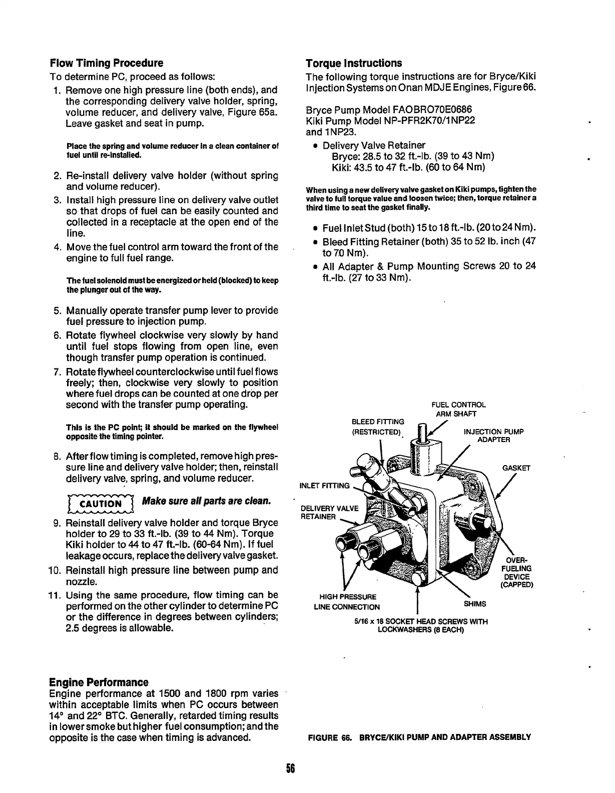
Torque Instructions
The following torque instructions are for Bryce/Kiki
Injection Systemson Onan MDJE Engines, Figure66.
Bryce Pump Model FAOBR070E0686
Kiki Pump Model NP-PFR2K70/1NP22
and
1
NP23.
0
Delivery Valve Retainer
Bryce: 28.5 to 32 ft.-lb. (39 to 43 Nm)
Kiki: 43.5 to 47 ft.-lb. (60 to 64 Nm)
When using a new deliveryvalvegasket
on
Kiki
pumps,
tighten the
valve
lo
full torque value and loosen twice; then, torque retainer a
third time to seat the gasket finally.
0
Fuel Inletstud (both)
15
to18ft.-lb. (20to24Nm).
0
Bleed Fitting Retainer (both) 35 to 52 Ib. inch (47
0
All
Adapter
&
Pump Mounting Screws 20 to 24
to
7.0
Nm).
ft.-lb. (27 to 33 Nm).
FUEL
CONTROL
ARM
SHAFT
BLEED
FITTING
(RESTRICTED)
fl/
INJECTION
PUMP
INLET FITTING
DELIVERY
VALVE
RETAINER
SHIMS
T
HIGH
PRESSURE
LINE
CONNECTION
5/16
x
18
SOCKET
HEAD
SCREWS
WITH
LOCKWASHERS
(8
EACH)
Engine Performance
Engine performance
at
1500
and 1800 rpm varies
within acceptable limits when
PC
occurs between
14' and 22' BTC. Generally, retarded timing results
in lower smoke but higher fuel consumption; and the
opposite is the case when timing is advanced.
FIGURE
66.
BRYCWKIKI
PUMP AND ADAPTER ASSEMBLY
56
Redistribution or publication of this document,
by any means, is strictly prohibited.