.
B.
C.
D.
E.
F.
G.
VALVE
VALVE SEAT
Rev.
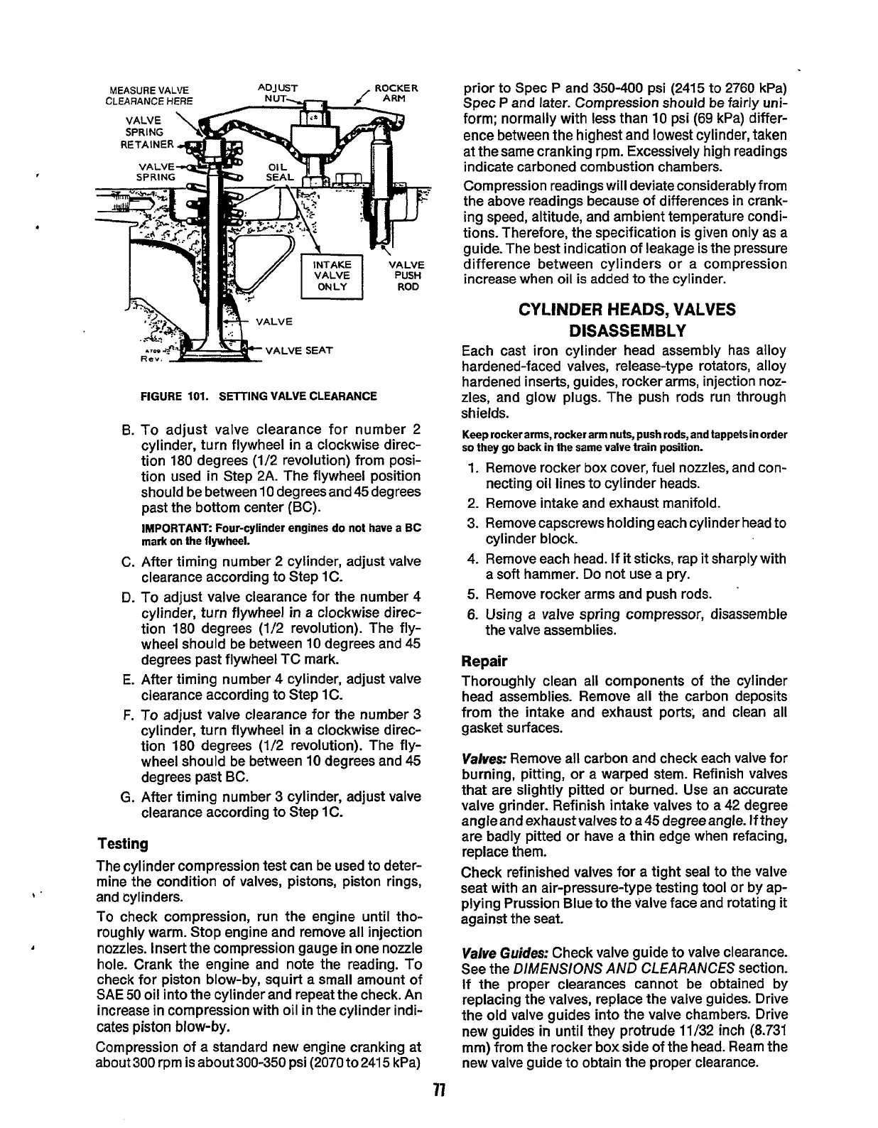
FIGURE
101.
SETTING
VALVE
CLEARANCE
To adjust valve clearance for number 2
cylinder, turn flywheel
in
a clockwise direc-
tion 180 degrees (1/2 revolution) from posi-
tion used in Step 2A. The flywheel position
should be between 10 degrees and 45 degrees
past the bottom center (BC).
IMPORTANT:
Four-cylinder engines
do
not have a
BC
mark on the
flywheel.
After timing number 2 cylinder, adjust valve
clearance according to Step 1C.
To adjust valve clearance for the number 4
cylinder, turn flywheel
in
a clockwise direc-
tion 180 degrees (1/2 revolution). The fly-
wheel should be between 10 degrees and
45
degrees past flywheel TC mark.
After timing number 4 cylinder, adjust valve
clearance according
to
Step IC.
To
adjust valve clearance for the number
3
cylinder, turn flywheel
in
a clockwise direc-
tion 180 degrees (1/2 revolution). The fly-
wheel should be between
10
degrees and 45
degrees past BC.
After timing number
3
cylinder, adjust valve
clearance according to Step
1
C.
Testing
The cylinder compression test can be used to deter-
mine the condition of valves, pistons, piston rings,
and cylinders.
To check compression, run the engine until tho-
roughly warm. Stop engine and remove all injection
nozzles. Insert the compression gauge
in
one nozzle
hole. Crank the engine and note the reading. To
check for piston blow-by, squirt a small amount of
SAE
50
oil into the cylinder and repeat the check. An
increase in compression with oil in the cylinder indi-
cates piston blow-by.
Compression of a standard new engine cranking at
about
300
rpm is about 300-350 psi (2070 to 241
5
kPa)
77
prior to Spec P and 350-400 psi (2415 to 2760 kPa)
Spec
P
and later. Compression should be fairly uni-
form; normally with less than 10 psi
(69
kPa) differ-
ence between
the
highest and lowest cylinder, taken
at the same cranking rpm. Excessively high readings
indicate carboned combustion chambers.
Compression readings
will
deviate considerably from
the above readings because of differences in crank-
ing speed, altitude, and ambient temperature condi-
tions. Therefore,
the
specification is given only
as
a
guide. The best indication of leakage is the pressure
difference between cylinders or a compression
increase when oil
is
added to the cylinder.
CYLINDER
HEADS,
VALVES
DISASSEMBLY
Each cast iron cylinder head assembly has alloy
hardened-faced valves, release-type rotators, alloy
hardened inserts, guides, rocker arms, injection noz-
zles, and glow plugs. The push rods run through
shields.
Keep
rockerarms, rocker arm nuts, push
rods,
and tappets in order
so
they
go
back in the same
valve
train position.
1.
Remove rocker box cover, fuel nozzles, and con-
necting oil lines to cylinder heads.
2. Remove intake and exhaust manifold.
3.
Remove capscrews holding each cylinder head
to
cylinder block.
4.
Remove each head. If
it
sticks, rap
it
sharply with
a
soft
hammer. Do not use a pry.
5.
Remove rocker arms and push rods.
6.
Using a valve spring compressor, disassemble
'
the valve assemblies.
Repair
Thoroughly clean all components of the cylinder
head assemblies. Remove all the carbon deposits
from
the
intake and exhaust ports, and clean all
gasket surfaces.
Valves:
Remove all carbon and check each valve for
burning, pitting, or a warped stem. Refinish valves
that are slightly pitted or burned. Use an accurate
valve grinder. Refinish intake valves to a 42 degree
angle and exhaust valves to a45 degree angle. If they
are badly pitted or have a
thin
edge when refacing,
replace them.
Check refinished valves for a tight seal to the valve
seat with an air-pressure-type testing tool or by ap-
plying Prussion Blue to the valve face and rotating
it
against the seat.
Valve
Guides:
Check valve guide to valve clearance.
See the DIMENSIONS AND CLEARANCES section.
If the proper clearances cannot be obtained by
replacing the valves, replace
the
valve guides. Drive
the old valve guides into the valve chambers. Drive
new guides
in
until they protrude
11/32
inch (8.731
mm) from the rocker box side of the head. Ream the
new valve guide to obtain the proper clearance.
Redistribution or publication of this document,
by any means, is strictly prohibited.
 Loading...

