Valve
Seafs:
If valve seats are pitted, refinish them.
Using conventional seat-grinding equipment, reface
each seat to a 45 degree angle and a seat width of
0.047
to 0.062 inch
(1.191
to 1.588 mm). You should
be able to reface each seat several times before it
becomes necessary to replace it.
If the valve seats are loose or cannot be refaced,
replace them.
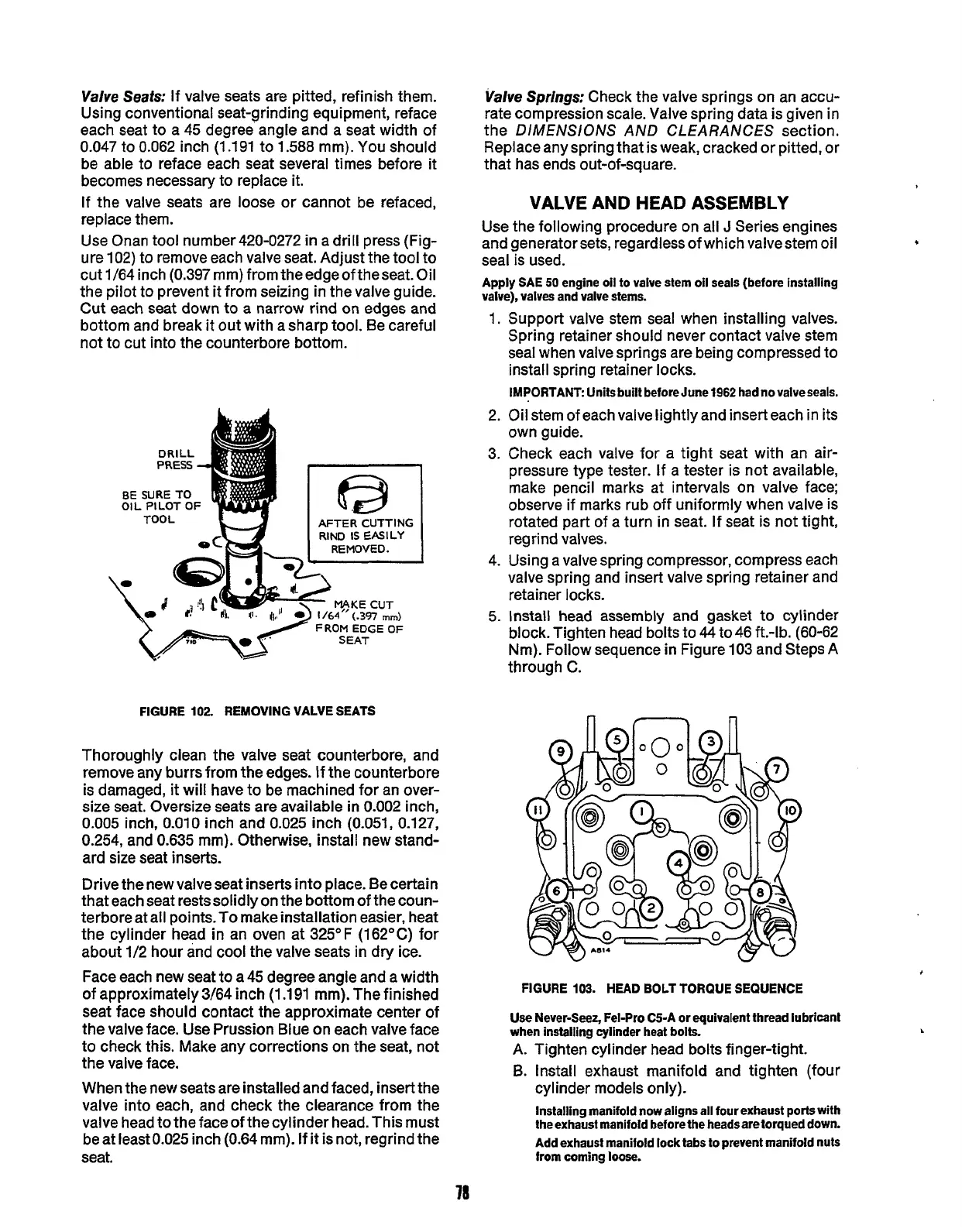
Use Onan tool number420-0272
in
a drill press (Fig-
ure 102) to remove each valve seat. Adjust the tool to
cut 1/64inch
(0.397mm)fromtheedgeoftheseat.Oil
the pilot to prevent it from seizing in the valve guide.
Cut each seat down to a narrow rind
on
edges and
bottom and break it out with a sharp tool. Be careful
not to cut into the counterbore bottom.
BE
SURE
TO
FROM
EDGE
OF
FIGURE
102.
REMOVING VALVE SEATS
Thoroughly clean the valve seat counterbore, and
remove any burrs from the edges. If
the
counterbore
is damaged,
it
will have to be machined for an over-
size seat. Oversize seats are available
in
0.002
inch,
0.005
inch, 0.010 inch and 0.025 inch (0.051, 0.127,
0.254, and 0.635 mm). Otherwise, install new stand-
ard size seat inserts.
Drive the new valve seat inserts into place. Be certain
that each seat restssolidly on the bottom of the coun-
terbore at all points.
To
make installation easier, heat
the cylinder head in an oven at 325°F (162OC) for
about 1/2 hour and cool the valve seats
in
dry
ice.
Face each new seat to a 45 degree angle and a width
of approximately 3/64 inch (1.191 mm). The finished
seat face should contact the approximate center of
the valve face. Use Prussion Blue on each valve face
to check this. Make any corrections on the seat, not
the valve face.
When the new seats are installed and faced, insert the
valve into each, and check the clearance from the
valve head to the face
of
the cylinder head.This must
be at least0.025 inch (0.64 mm). If
it
is not, regrind the
seat.
Valve
Springs:
Check the valve springs on an accu-
rate compression scale. Valve spring data is given in
the DIMENSIONS AND CLEARANCES section.
Replace any spring that is weak, cracked or pitted, or
that has ends out-of-square.
VALVE AND HEAD
ASSEMBLY
Use the following procedure on all
J
Series engines
and generator sets, regardless of which valvestem oil
seal
is
used.
Apply SAE
50
engine oil to valve stem oil seals (before installing
valve), valves and valve stems.
1.
2.
3.
4.
5.
Support valve stem seal when installing valves.
Spring retainer should never contact valve stem
seal when valve springs are being compressed to
install spring retainer locks.
IMPORTANT: Units built before June
1962
had
no
valveseals.
Oil stem of each valve lightly and insert each in its
own guide.
Check each valve for a tight seat with an air-
pressure type tester. If a tester is not available,
make pencil marks at intervals on valve face;
observe if marks rub off uniformly when valve is
rotated part of a turn
in
seat. If seat is not tight,
regrind valves.
Using a valve spring compressor, compress each
valve spring and insert valve spring retainer and
retainer locks.
Install head assembly and gasket to cylinder
block. Tighten head bolts to
44
to46 ft.-lb. (60-62
Nm). Follow sequence
in
Figure 103 and Steps A
through C.
n
n
FIGURE
103.
HEAD
BOLT TORQUE SEQUENCE
Use
Never-Seez, Fel-Pro C5-A
or
equivalent thread lubricant
when installing cylinder heat bolts.
A. Tighten cylinder head bolts finger-tight.
B.
Install exhaust manifold and tighten (four
cylinder models only).
Installing manifold now aligns all four exhaust
ports
with
the exhaust manifold heforethe heads are torqued down.
Add exhaust manifold lock tabs to prevent manifold nuts
from coming
loose.
.
78
Redistribution or publication of this document,
by any means, is strictly prohibited.
 Loading...

