C.
Tighten cylinder head bolts in sequence
shown in Figure 103 to
25-30
ft.-lb. (34-41
Nm).
D.
Tighten cylinder head bolts in samesequence
to
44-46
ft.4
b.
(60-62
N
m) .
E.
After
60
seconds, retighten cylinder head
bolts in sequence to 44-46
ft.-lb.
(60-62
Nm).
This step compensates for the compress of
the
cylinder gasket.
Install intake manifold, nozzles, glow plugs, and
oil lines.
Install valve stem cap.
Install push rods, rocker arms, and rocker arm
nuts.
Set valve clearance. See Figure
101.
IMPORTANT: Afler the first
50
hours of operation, retighten
the cylinder head bolts and check valve clearance.
VALVE ROTATOR CLEARANCE
Both the intake and the exhaust valves on all Onan
J
Series engines are equipped with release-type valve
rotators. The cap covering each valve
tip
releases
keeper tension as thevalve is pushed
off
itsseat.This
allows the valve to float
in
its guide. Engine vibration
and cylinder air flow cause the valve to rotate while
floating.
To assure proper operation of thissystem,valvestem
tip-to-cap clearance should be checked every
5000
hours, or whenever the parts are exposed or removed.
Clearance must be maintained at
0.001
to
0.005
inch
(0.025 to 0.127 mm). Too
little
clearance will prevent
valve rotation, increasing the possibility of valve
leakage and engine power
loss.
Too much clearance
can lead to valve breakage.
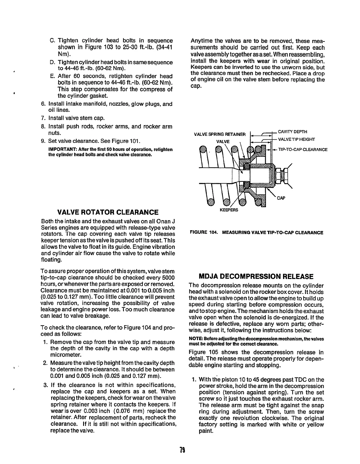
To
check the clearance, refer to Figure
104
and pro-
ceed as follows:
1. Remove the cap from the valve tip and measure
the depth of the cavity in the cap with a depth
micrometer.
2. Measure thevalve tip height from thecavity depth
to determine the clearance. It should be between
0.001 and
0.005
inch
(0.025
and 0.127 mm).
3.
If the clearance is not within specifications,
replace the cap and keepers as a set. When
replacing the keepers, check for wear on thevalve
spring retainer where it contacts the keepers. If
wear is over
0.003 inch (0.076 mm) replace the
retainer. After replacement of parts, recheck the
clearance. If it is still not within specifications,
replace the valve.
Anytime the valves are to be removed, these mea-
surements should be carried out first. Keep each
valveassembly together as aset.
When
reassembling,
install the keepers with wear in original position.
Keepers can be inverted to use the unworn side, but
the clearance must then be rechecked. Place a drop
of engine oil on the valve stem before replacing the
cap.
VALVE
SPRING
RETAINER
DEPTH
HEIGHT
LP
CLEARANCE
FIGURE
104.
MEASURING VALVE TIP-TO-CAP CLEARANCE
MDJA DECOMPRESSION RELEASE
The decompression release mounts on the cylinder
head with a solenoid on the rocker box cover.
It
holds
the exhaust valve open to allow the engine to build up
speed during starting before compression occurs,
and tostop engine.The mechanism holds the exhaust
valve open when the solenoid is de-energized. If the
release is defective, replace any worn parts; other-
wise, adjust
it,
following the instructions below:
NOTE
Beforeadjusting thedecompression mechanism, thevalves
must be adjusted
for
the
correct
clearance.
Figure 105 shows the decompression release in
detail. The release must operate properly for depen-
dable engine starting and stopping.
1.
With the piston
10
to
45
degrees past TDC on the
power stroke, hold the arm
in
the decompression
position (tension against spring). Turn the set
screw
so
it
just touches the exhaust rocker arm.
The release arm must be tight against the snap
ring during adjustment. Then, turn the screw
exactly one revolution clockwise. The original
factory setting is marked with white or yellow
paint.
79
Redistribution or publication of this document,
by any means, is strictly prohibited.
 Loading...

