INTERNAL DISASSEMBLY
If
engine disassembly is necessary, observe the fol-
lowing order (Le. Flywheel, Gear Cover...).
As
disas-
sembly progresses, the order may be changed some-
what as will be self-evident. The engine assembly
procedure
is
the reverse of disassembly. Any special
assembly instructions for a particular group are
included
in
the applicable section. When reassem-
bling, check each section for these special assembly
instructions or procedures.
FLYWHEEL
Remove the blower housing.Theflywhee1 isatapered
fit on the crankshaft. Improvise a puller, using at least
a 7/16 inch (11.113 mm) bar, and drill two 7/16 inch
(1 1.1 13 mm) holes2-7/8 inches
(73.025 mm) between
centers. Loosen the flywheel mounting screw a few
turns. Place bar againstthe flywheelscrew and attach
bar, using two 3/8-16 thread screws in the holes pro-
vided in flywheel. Alternately tighten the screws until
flywheel
is
free.
PISTON
DROP
Inches
I
mm
REPLACEMENT
Replacement flywheels are supplied without the tim-
ing markings becauseeach flywheel must befitted to
its engine. The only accurate method of determining
the top dead center (TDC) and port closing
(PC)
points is to measure the piston travel. This is acritical
measurement and should be attempted only with
accurate, reliable equipment.
With the flywheel mounted, remove the head and
install a depth gauge over the front piston. Rotate the
flywheel to find theTDC position on the compression
stroke, and markthis point on theflywheel. Next, turn
the flywheel counterclockwise until the piston drop is
as specified in Table 9. Mark both
TDC and piston
drop to PC point on the flywheel.
PORT
BTC
ENGINE CLOSING
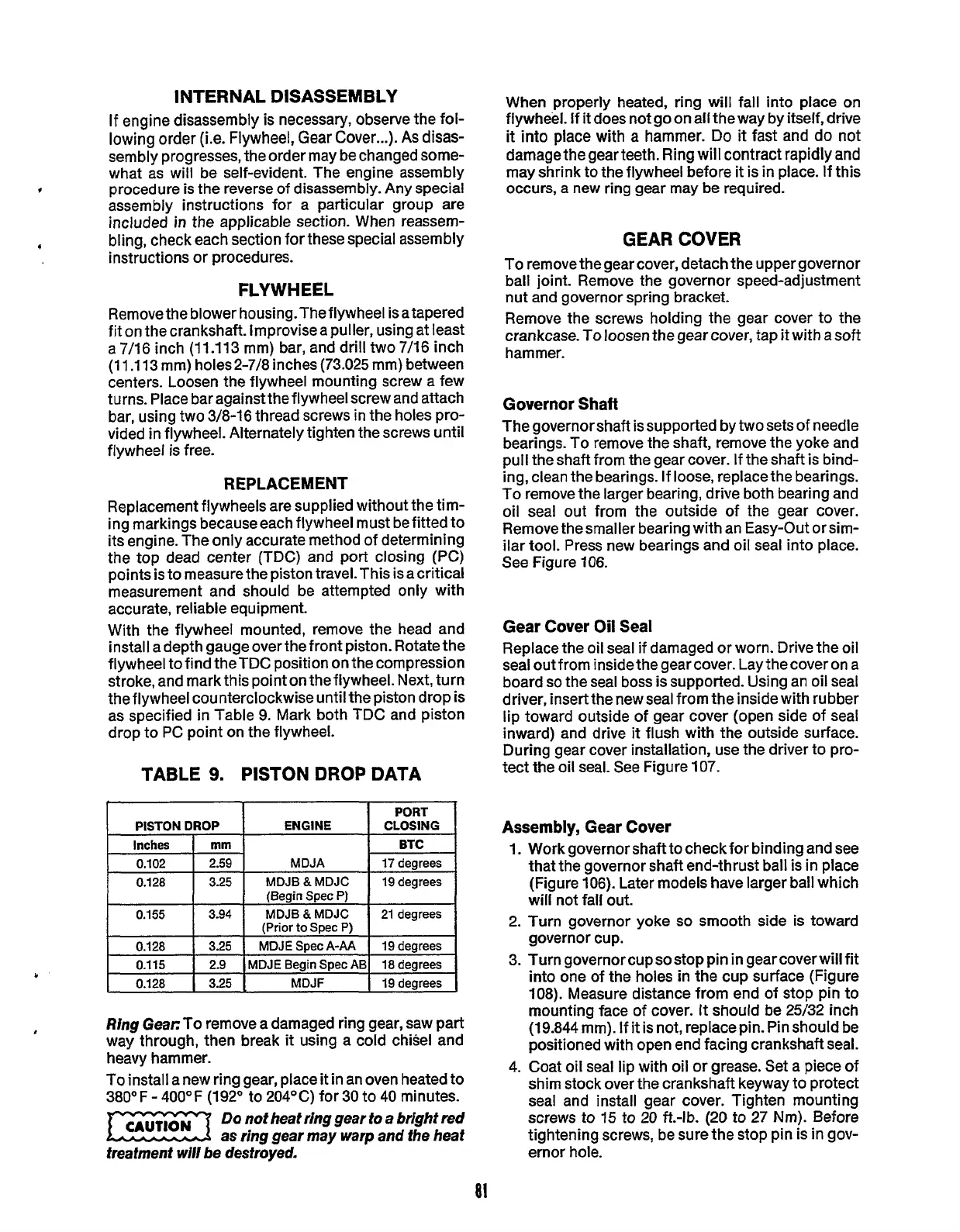
TABLE
9.
PISTON DROP DATA
0.102
I
2.59
I
MDJA
I
17degrees
0.128
I
3.25
I
MDJB&MDJC
I
19degrees
(Begin Spec
P)
(Prior
to
Spec
P)
0.155
0.128
0.115
0.128 3.25
MDJF
19 degrees
Ring Gear:
To
remove a damaged ring gear, saw part
way through, then break
it
using a cold chisel and
heavy hammer.
To install a new ring gear, place
it
in an oven heated to
380°
F
-
400OF (192O to 204OC) for
30
to
40
minutes.
Do
not heat ring gear to a bright red
as ring gear may warp and the beat
treatment wiN be destroyed.
When properly heated, ring will fall into place
on
flywheel. If
it
does not go on all theway by itself, drive
it
into
place with
a
hammer.
Do
it
fast and do not
damagethe gear teeth. Ring will contract rapidly and
may shrink to the flywheel before
it
is
in
place. If this
occurs,
a
new
ring gear may be required.
GEAR
COVER
To remove the gear cover, detach the upper governor
ball joint. Remove the governor speed-adjustment
nut and governor spring bracket.
Remove the screws holding the gear cover to the
crankcase. To loosen the gear cover, tap
it
with asoft
hammer.
Governor Shaft
The governor shaft is supported by
two
sets of needle
bearings. To remove the shaft, remove the yoke and
pull the shaft from the gear cover. If the shaft is bind-
ing, clean the bearings. If loose, replacethe bearings.
To remove
the
larger bearing, drive both bearing and
oil seal out from the outside of the gear cover.
Remove thesmaller bearing with an Easy-Out orsim-
ilar tool. Press new bearings and oil seal into place.
See Figure
106.
Gear
Cover
Oil
Seal
Replace the oil seal if damaged or worn. Drive the oil
seal out from inside
the
gear cover. Lay the cover on a
board
so
the seal boss is supported. Using an oil seal
driver, insertthe new seal from
the
inside with rubber
lip toward outside of gear cover (open side of seal
inward) and drive
it
flush with the outside surface.
During gear cover installation, use the driver to pro-
tect the oil seal. See Figure
107.
Assembly, Gear Cover
1.
2.
3.
4.
Work governor shaft to check for binding and see
that the governor shaft end-thrust ball is in place
(Figure 106). Later models have larger ball which
will not fall out.
Turn governor yoke
so
smooth side is toward
governor cup.
Turn governorcupsostop pin
in
gearcoverwill fit
into one of the holes in
the
cup surface (Figure
108). Measure distance from end of stop pin to
mounting face of cover.
It
should be 25/32 inch
(19.844 mm).
If
it
is not, replace
pin.
Pin should be
positioned with open end facing crankshaft seal.
Coat oil seal lip with oil or grease. Set a piece of
shim stock over the crankshaft keyway to protect
seal and install gear cover. Tighten mounting
screws to
15
to
20
ft.-lb.
(20
to 27
Nm).
Before
tightening screws, be sure
the
stop pin is in gov-
ernor hole.
Redistribution or publication of this document,
by any means, is strictly prohibited.
 Loading...

