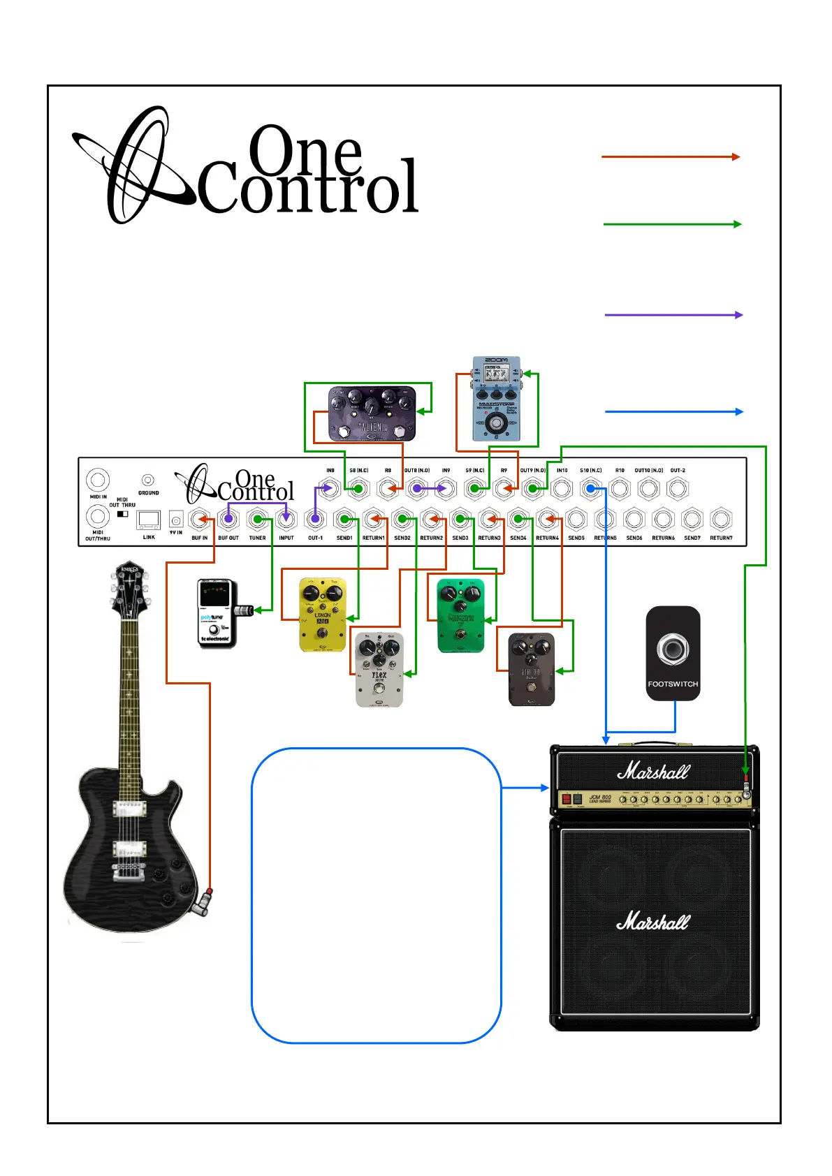
KEY
All red lines are cables
taking signal into OC10
All green lines are cables
taking signal out of OC10
All purple lines are cables
taking signal out of OC10
and immediately back Into
OC10 (Links)
All blue lines are cables used
for control switching
(Channel, Reverb On/Off etc)
and do not carry signal
OC10 setup utilising BJF buffer Circuit, 4 loops from Loops
1 Thru 7, Loops 8 And 9 for effects and Loop 10, S10 (N.C)
socket for amp channel switching.
SETUP 3
PAGE 1
Using footswitchable facilities or control switch-
ing or “CTRL” as it is commonly abbreviated
can be done by utilising the Send (S) and Out
sockets on loops 8, 9 and 10. The terms listed
next to the sockets refer to a footswitch status,
(N.C) being normally closed, and (N.O) being
normally open. Manufacturers of amplifiers
and effects units do not always list what status
there CTRL/Footswitch sockets are in so it is
necessary to connect these sockets individu-
ally to see how they react and which is prefer-
able to the user. (please see page 2 for more
information)
NOTE, Loops can only be used as one of the
two functions, either as a loop for an effects
unit, or as a control switch.
To footswitch input rear amp
UTILISING FOOTSWITCHING
(Control Switching)