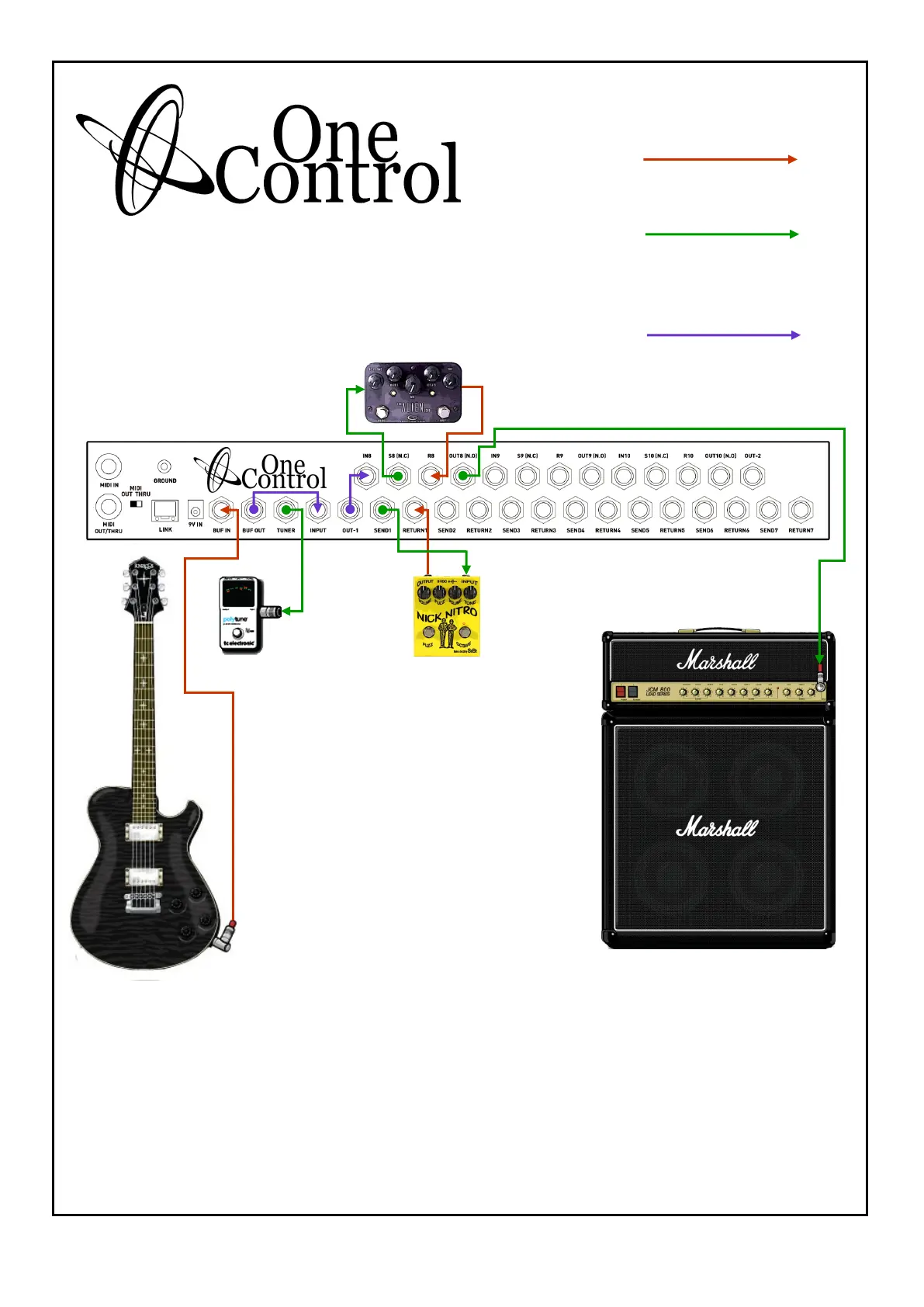
KEY
All Red Lines Are Cables
Taking Signal Into OC10
All Green Lines Are Cables
Taking Signal Out Of OC10
All Purple Lines Are Cables
Taking Signal Out of OC10
and Immediately Back Into
OC10
OC10 Setup Utilising Buffer Circuit, 1 Loop
from Loops 1 thru 7 and Loop 8
The above setup is using the OC10 with the guitar running into the Buffer circuit, Tuner out, loop 1
and loop 8
Utilising the Buffer circuit will give the signal increased strength and retention of clarity, primarily this
circuit is designed for running longer cable runs and running through multiple effects units which ulti-
mately can lower signal strength and dull the top end of the signal.
Loop 1 is being utilised in this example. loops 1 thru 7 are internally connected so signal from main
input will always be running to OUT 1 and OUT 2 whether pedals are connected or not.
SETUP 2
PAGE 1