Do you have a question about the Onkyo M-5030 and is the answer not in the manual?
Identifies critical components for fire/shock risk and emphasizes using genuine Onkyo parts for replacement.
Perform leakage-current or resistance measurements to verify insulation before returning unit to customer.
Details power output, distortion levels, frequency response, input sensitivity, and damping factor.
Covers input/output types, semiconductor count, dimensions, and weight.
Diagram showing internal functions of the TA7317P integrated circuit.
Diagram illustrating the functional blocks within the TA7318P integrated circuit.
Schematic representation of the NJM4558DX operational amplifier's internal circuitry.
Instructions for replacing fuses, emphasizing using the same type and rating for fire/shock protection.
Lists part numbers for protection and speaker lamps used in the unit.
Specifies testing insulation resistance using a 500V tester, requiring >10MΩ.
Guide to operating the voltage selector switch on the rear panel for correct power supply matching.
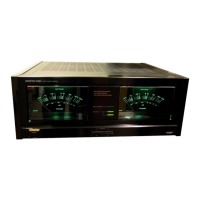
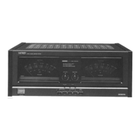
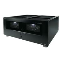
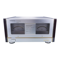
Identifies front panel elements including power switch, meters, and indicators.
Steps before adjustments: level surface, ventilation, no load/signal, calm air.
Procedure to align meter needles to zero using the adjustment screw when power is off.
Adjusting semi-fixed resistor R441 to set voltage between VCT-IID to 14mV after warm-up.
Adjusting semi-fixed resistor R639 to align meter needles to zero with no signal present.
Applying a 1kHz signal and adjusting R611/R612 to set meter reading to 0dB.
Diagram illustrating how to connect speakers and a preamplifier to the power amplifier.
Visual representation of the unit's parts disassembled for servicing or identification.
Comprehensive list of parts, including reference numbers, part numbers, and descriptions for repair and maintenance.
Instructions and diagrams detailing how to pack the unit for shipping or storage.
Details components for the Protector/Power Supply PC Board (NAPS-1713/1713a/1713b).
Lists components for the Meter Drive Circuit PC Board (NAME-1717).
Includes parts for Speaker Terminal (NAOP-1714/1715) and Meter Lamp (NAPL-1719/1720) boards.
Lists components for the Temperature Correction PC Board (NARB-1721), including thermistors and resistors.
Detailed list of transistors, diodes, capacitors, resistors, and radiators for the Power Amplifier PC Board (NAMA-1780).
Detailed circuit schematic for the 120V model, showing all components and connections.
Detailed circuit schematic for the 220V model, illustrating component placement and wiring.
Visual guides showing component placement on various printed circuit boards for identification and assembly.