EasyManua.ls Logo

Onkyo M-5060 Service Manual

Onkyo M-5060
13 pages
To Next Page IconTo Next Page
Page #1 background imageLoading...
Page #1 background image

Other manuals for Onkyo M-5060

Question and Answer IconNeed help?

Do you have a question about the Onkyo M-5060 and is the answer not in the manual?

Onkyo M-5060 Specifications

General IconGeneral
TypeStereo Power Amplifier
Power Output140 watts per channel into 8Ω (stereo)
Frequency Response20Hz to 20kHz
Input Sensitivity1V
Signal-to-Noise Ratio120 dB
Dimensions480 x 185 x 424mm
Weight22.5kg
Damping Factor140
Total harmonic distortion0.005%
Speaker load impedance4-16 ohms

Summary

Specifications

Features

Dual Super-Servo System

Controls positive/negative signal path, reduces distortion from power supply and ground.

Linear Switching System

Uses high FT transistor in output stage to eliminate switching distortion.

High Quality and High Power

120 watts per channel with 0.003% distortion, based on dual super-servo design.

Quick Responding, Large Peak Meters

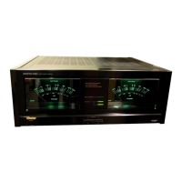
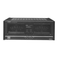
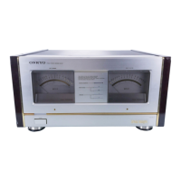
Features 65mm needles for transient killer and protection circuit monitoring.

Dual Super-Servo System Power Section

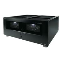
Forms the power section for P-3060 Dual Super-Servo amp system.

Dual Power Supply - Dual Monaural Amp Construction

Uses two large power supplies for enhanced musical purity.

Block Diagram

Circuit Description

Dual Super-Servo

Explains how the dual super-servo system eliminates ultralow frequency noise and ground impedance distortion.

Adjustments

Preparations

Steps for setting up the unit for adjustments, including ventilation and level positioning.

Adjusting the meter to ZERO

Procedure to set the meter needle to zero when the power supply is OFF.

Adjusting idling current

Procedure to adjust idling current to 12mV (or 16mV) on board NAMA-752.

Adjusting meter offset

Procedure to adjust meter offset to zero after power supply is ON and without signal input.

Meter level adjustment

Procedure to adjust meter level to zero using a 1kHz test signal at speaker output 9.8V.

Connection Diagram

Component Location

Component Location - Parts List

Precautions

Super Servo Switch

Details the function and factory setting of the dual super servo switch.

Exploded View

Exploded View – Parts List

Schematic Diagram

Power Amplifier PC Board View from Bottom Side

Power Amplifier PC Board (NAMA-752) - Parts List

Headphone Amplifier PC Board (NAHP-753) - Parts List

Protector and Rectifier PC Board View from Bottom Side

Protector and Rectifier Circuit PC Board (NAPS-749) - Parts List

Switch Circuit PC Board (NASW-754a) - Parts List

Meter Drive Circuit PC Board View from Bottom Side

Speaker Selector Switch PC Board (NASW-755b) – Parts List

Meter Drive Circuit PC Board (NAME-758) – Parts List

Lamp Circuit PC Board (NAPL-756) – Parts List

Lamp Circuit PC Board (NAPL-757) – Parts List

Packing Procedures

Packing Procedures – Parts List 120V Model

Packing Procedures – Parts List 220V Model

Related product manuals