SL-105
2 Confirming operations
1 Adjustment of idling current
3 The setting position before shipment
.
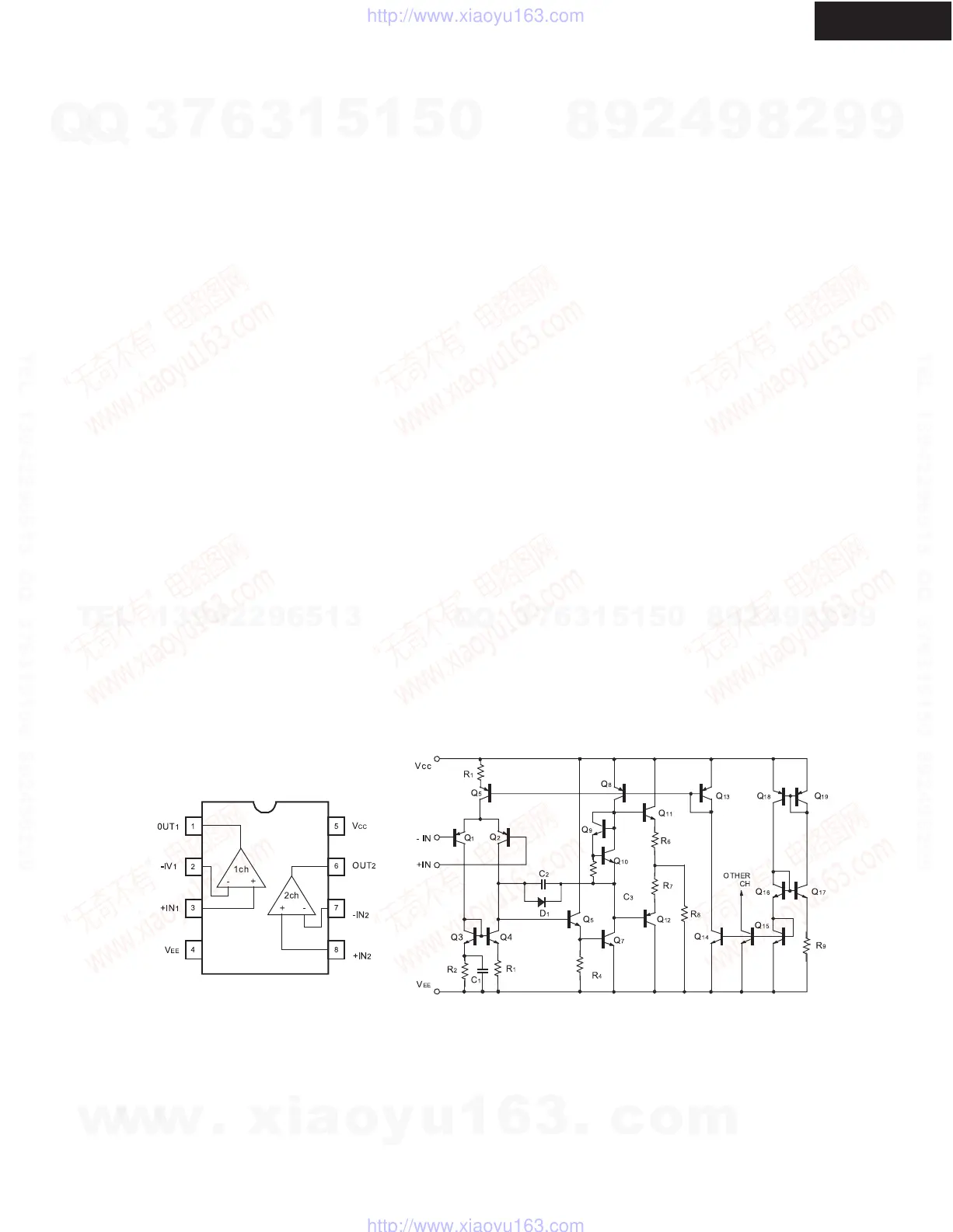
IC BLOCK DIAGRAM
ADJUSTMENT PROCEDURES AND SETTING POSITION
a. Set the voltage at P531 to 0.25mV by adjusting R544 under the condition of no input and no load.
(Auto standby switch is off position.)
b. Set the voltage at P531 to 6mV by adjusting R544 after 5 minutes heat running.
2-1. Confirming operation of auto standby On / Off.
a. Auto standby switch is On position.
b. After 10 seconds when the input signal is no signal and power switch is ON,
shorting for P604, check the LED
color changes red to green.
c. When the unit is POWER ON and LED color is green, shorting for P623, check the LED color
changes green to red.
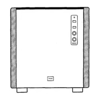
(Front panel)
OUTPUT LEVEL MIN
CROSSOVER FREQUENCY MAX
POWER SWITCH OFF
(Rear panel)
AUTO STANDBY SWITCH ON
BA15218
w
w
w
.
x
i
a
o
y
u
1
6
3
.
c
o
m
Q
Q
3
7
6
3
1
5
1
5
0
9
9
2
8
9
4
2
9
8
T
E
L
1
3
9
4
2
2
9
6
5
1
3
9
9
2
8
9
4
2
9
8
0
5
1
5
1
3
6
7
3
Q
Q
TEL 13942296513 QQ 376315150 892498299
TEL 13942296513 QQ 376315150 892498299
http://www.xiaoyu163.com
http://www.xiaoyu163.com
 Loading...