EVBUM2868/D
www.onsemi.com
4
HARDWARE SETUP
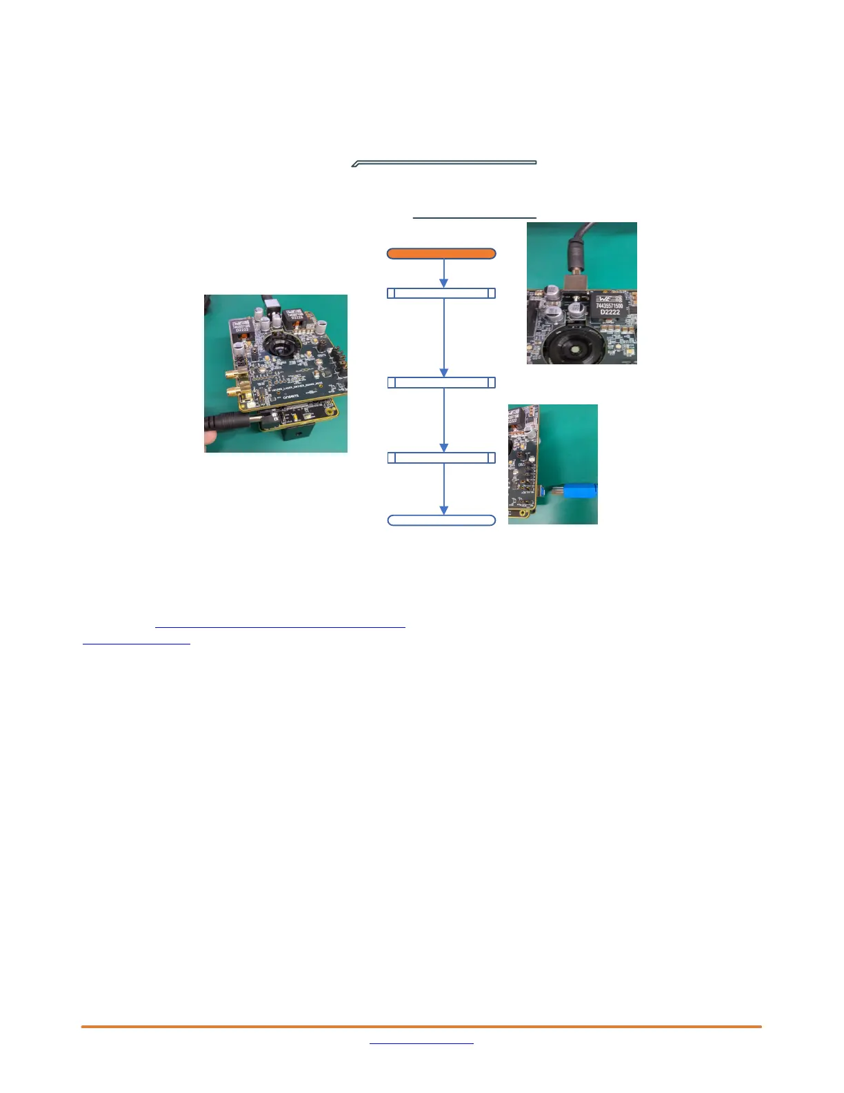
Figure 4 illustrates the suggested power off sequence
for the power supplies and USB connection. It is
recommended to remove the 12 V laser supply connection
first or together with the headboard. For the power up
sequence, we recommend to make the USB connection last
and wait several second before starting devware.
Figure 4. Power Off Sequence
DC5V4A Disconnect
DC12V9A Disconnect
End
DevWareX Close
POWER OFF
For AF0130
MG ports
USB Disconnect
For VCSEL
(Laser Board)
DEVWAREX INSTALLATION
The latest version of DevwareX can be downloaded from
the website: https://www.onsemi.com/download/software/
zip/devsuite_sw.zip
The specific sensor setup can be found on the image
sensor portal under NDA: Portal Home > Pre−Production
Products > AF, AP, AR, AS > AF0130
HardwareUpdate Tool
The current software uses a different FPGA version
(0x14D) compared to the latest default for other sensors
(0x4C) working with DevwareX. Your kit should come with
correct version on demo3 for operating the AF0131 sensor
and therefore the demo3 FPGA most probably does NOT
need to be updated. If the demo3 FPGA version does
need to be updated, this version may need to be selected
manually from the C:/Aptina Imaging/fpga folder in
the HardwareUpdate Tool.
DEVWAREX STARTUP WIZARD
Figure 5 will guide you through the startup wizard of
DevwareX. Currently the AF0130−REV1.xsdat file should
be selected manually in the sensor data folder because the
Two−Wire interface is needed for auto−detection of the
sensor after startup. See below limitation on Two−Wire
Serial Interface for more details on this. After this the usual
procedure of running the Demo Initialization should get you
up and running. The AF0131 only has the option to output
RAW interleaved data on the main window. Therefore the
plug−in should be started to show the calculated depth,
intensity and amplitude images.
 Loading...