Do you have a question about the Opal-RT OP5707XG and is the answer not in the manual?
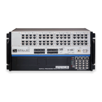
The OP5707XG is a sophisticated simulator designed for real-time simulation, offering robust features for both functionality and maintenance. Its primary function is to provide a platform for testing system signals and running complex simulations, particularly in environments where precise timing and signal integrity are critical. The device is built to integrate seamlessly into existing setups, whether as a standalone unit on a shelf or desktop, or installed within a traditional rack.
The OP5707XG serves as a core component in real-time simulation systems, enabling users to test and validate designs under various conditions. It supports a range of connectivity options to facilitate its integration into a broader simulation environment.
One of its key functions is to provide a robust grounding mechanism. Proper grounding is paramount for the OP5707XG, as it not only protects against electric shocks but also shields the device from voltage spikes, including those caused by lightning strikes. This enhanced immunity to electromagnetic interference (EMI) is achieved by lowering noise levels and emissions, ensuring stable and reliable operation. Users are instructed to connect a grounding cable from the OP5707XG ground screw to a secure ground point, typically a rack or strong earth. This connection is vital for preventing EMI-related damage to the simulator, especially when it is installed near other devices that might generate electromagnetic fields.
Network connectivity is another fundamental aspect of the OP5707XG's functionality. It connects to a host PC via a standard computer network jack, using a blue RJ45 cable. This connection allows for communication between the simulator and the host PC, which is essential for configuring simulations, transferring data, and monitoring performance. The manual explicitly warns against connecting the network cable to any jack other than the designated network jack, emphasizing the importance of correct setup for optimal performance and to avoid potential issues.
For testing system signals, the OP5707XG utilizes an I/O loopback kit. This kit is particularly useful for diagnostic purposes when no external signal source is available. The loopback kit includes a custom flat cable that matches OPAL-RT standard DB37 pin assignments, making connections straightforward. By connecting the flat cable from the loopback board to the simulator's DB37 Output signal and then to the simulator's DB37 Input signal, users can effectively loop signals back into the system for internal testing. This feature allows for comprehensive verification of the simulator's I/O capabilities without needing external hardware. The loopback board also requires a VUser connection to the OP5707XG to preserve isolation, highlighting the device's design for maintaining signal integrity.
Synchronization is a critical function for multi-chassis simulations. The OP5707XG offers two synchronization options: optical fiber (recommended for its superior performance) and legacy copper cable. The synchronization link is designed to be daisy-chained between all participating chassis. In this setup, one system is configured as the Master, with its synchronization cable connected to its TX output. Subsequent systems, configured as Slaves, connect their RX inputs to the TX output of the preceding system in the chain. This daisy-chain configuration ensures that all simulators operate in perfect synchronicity, which is crucial for accurate and coherent simulation results. For systems using an OP5707 and remote I/O chassis connected via MuSE, synchronization cables are not required, as the synchronization link is integrated into the MuSE link, simplifying the setup.
The device also includes a USB JTAG port, primarily for maintenance and reprogramming purposes. This port is used with a USB(A)-USB(B) cable to reprogram the FPGA (Field-Programmable Gate Array) in instances where programming has been lost or damaged. This function is typically performed under the guidance of technical support, ensuring that the device's core logic can be restored or updated as needed.
The OP5707XG is designed with user-friendliness and operational safety in mind, incorporating several features that enhance its usability.
The installation process is straightforward, beginning with placing the unit on a shelf, desktop, or within a rack. This flexibility allows it to adapt to various lab or industrial environments. Connecting the power cable to the nearest power outlet is a standard step, followed by the crucial grounding procedure. The manual emphasizes the importance of proper grounding by dedicating a specific section to it, detailing how to attach a flat braided grounding strap with ring terminals to the OP5707XG ground screw and then to the rack or earth. This meticulous attention to grounding underscores the device's focus on safety and EMI protection.
Network setup involves connecting the blue RJ45 cable to the designated Ethernet port on the OP5707XG and to the same network as the host PC. This ensures seamless communication for simulation control and data exchange. The clear instructions and warnings regarding the correct network jack help users avoid common setup errors.
For internal testing, the I/O loopback kit is a valuable usage feature. It allows users to quickly verify the functionality of the simulator's input and output signals. The custom flat cable and DB37 pin assignments simplify the connection process, making it accessible even for users who may not be deeply familiar with the internal workings of the device. The requirement to connect VUser from the loopback board to the OP5707XG to preserve isolation highlights the system's design for maintaining signal integrity during testing.
Synchronization options, whether optical fiber or copper cable, provide flexibility for multi-chassis setups. The daisy-chain method for synchronization is clearly explained, allowing users to configure complex simulation environments with multiple synchronized units. The recommendation for optical fiber indicates a preference for higher performance and reliability in synchronization.
The breakout board, which allows access to each pin of the DB37 separately through screw terminals, is another practical usage feature. This board simplifies the process of connecting individual signals, providing greater flexibility for custom setups and detailed signal analysis. Users can easily insert the breakout board DB37 connector onto the desired DB37 connector on the simulator, making it convenient to interface with various external components or measurement devices.
The OP5707XG incorporates several features that facilitate maintenance and ensure the long-term reliability of the device.
A primary maintenance feature is the emphasis on anti-static precautions. OPAL-RT strongly recommends the use of anti-static wrist straps whenever handling any electronic device provided by them. This measure is crucial for preventing electrostatic discharge (ESD), which can damage sensitive electronic components. By adhering to this recommendation, users can significantly reduce the risk of internal damage during installation, configuration, or any maintenance activities.
The manual also explicitly states the need to disconnect power before servicing the device. This is a fundamental safety and maintenance practice that prevents electrical shock and protects the device from accidental short circuits or damage during internal work. This clear instruction ensures that maintenance is performed in a safe and controlled manner.
The grounding mechanism, while primarily a functional feature, also serves as a critical maintenance aspect. By ensuring proper grounding, the device is protected from external electrical disturbances, which reduces the likelihood of component failure due to voltage spikes or EMI. Regular checks of the grounding connection can help maintain this protective barrier, contributing to the device's longevity and reliability.
The USB JTAG port is specifically designed for maintenance purposes, particularly for FPGA reprogramming. In situations where the FPGA programming is lost or damaged, this port allows technical support to restore the device's functionality. This feature is essential for recovering from software-related issues that might otherwise render the device inoperable, providing a robust mechanism for troubleshooting and repair. The instruction to contact technical support for FPGA programming issues indicates that this is a specialized maintenance task, ensuring that complex repairs are handled by experts.
The I/O loopback kit, while used for testing, also aids in maintenance by allowing users to diagnose signal path issues. If a problem is suspected with the simulator's inputs or outputs, the loopback kit can be used to isolate the issue, determining whether the problem lies within the simulator itself or with external connections. This diagnostic capability streamlines the troubleshooting process, reducing downtime and facilitating quicker repairs.
Overall, the OP5707XG is designed to be a reliable and maintainable real-time simulator, with clear instructions and features that support both its operational use and its long-term care.
| Model | OP5707XG |
|---|---|
| Number of CPU Cores | 8 |
| Processor | Intel Xeon |
| Storage | SSD |
| Operating System | Linux RT |
| Network Interface | Dual 10 GbE |
| FPGA | Xilinx Kintex |
| Expansion Slots | PCIe |
| Form Factor | Rackmount |