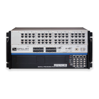
The synchronization link must be daisy-chained between all chassis participating in the simulation. The system which is configured to be the Master of the
synchronization in the RT-LAB or HYPERSIM software is the head of the daisy-chain, and the synchronization cable must be connected in the TX output
of this system.
The other end must be connected to the RX input of the second system to be synchronized (configured as Slave in the software). If there are more than
two systems to synchronize, another cable must be installed between the TX output of the second system and the RX input of the third system, etc. until
the last system.
The figure below shows the connection via optical fiber :
Note: Synchronization cables are not required between an OP5707 and remote I/O chassis connected via MuSE since the synchronization link is
integrated into the MuSe link.
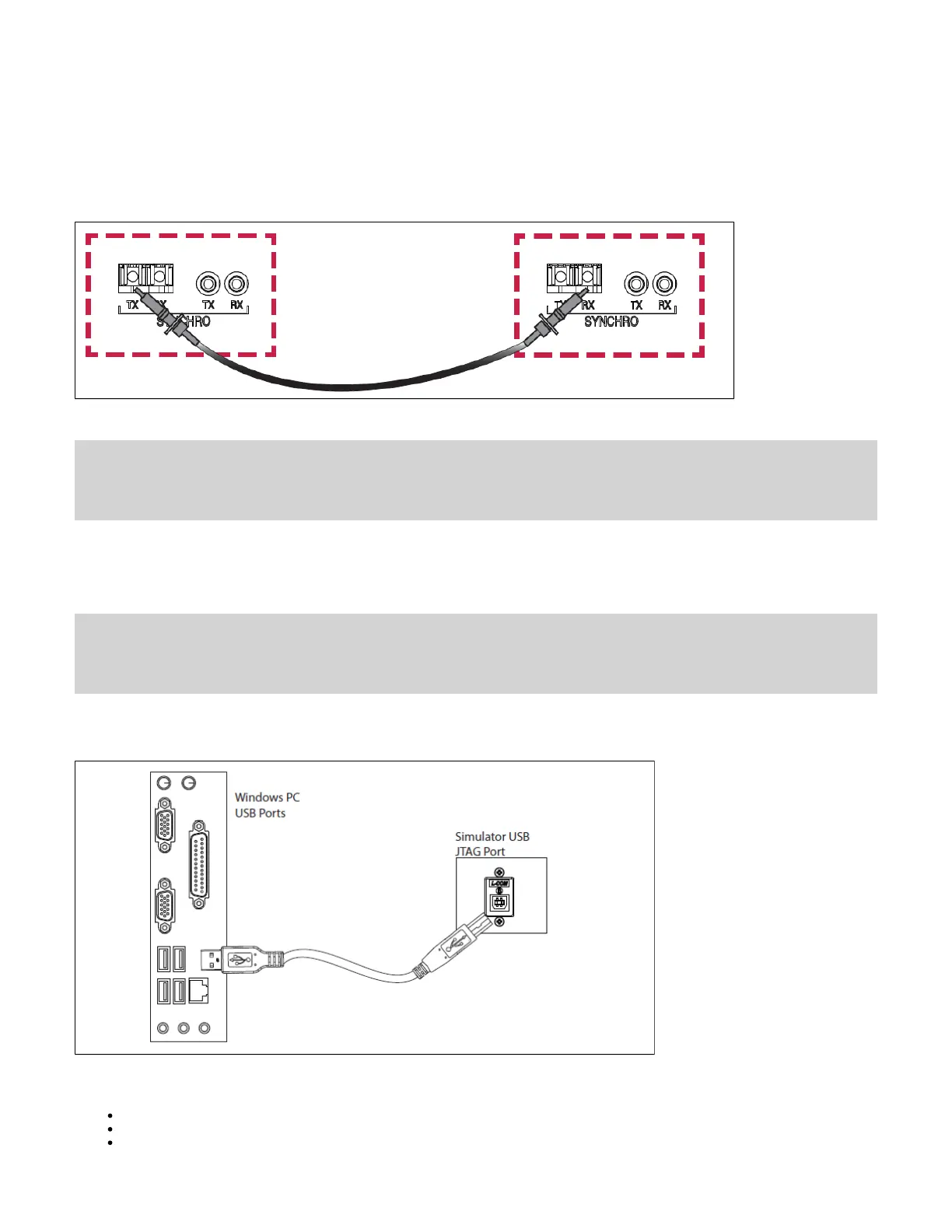
Connecting the USB Cable
The USB(A)-USB(B) cable is required only to reprogram the FPGA using the JTAG port when programming has been lost or damaged. Contact
Technical Support for all FPGA programming issues.
Connect one end to a Windows PC USB port and the other end to the USB JTAG port on the OPAL-RT simulator, then follow the technical support
representative’s instructions to reprogram the FPGA.
Connecting the Ground Screw
Connecting Network Cables
Connecting the I/O Loopback Kit
 Loading...