Fire Protection | Data sheet No. 41300 | Version 06-2012 | 7 | 9
Duct Smoke Detector KRM
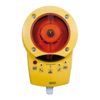
8. Installing the housing with the sensor
• Attach the housing bottom part with the electronics and sensor to the
adapter plate. The housing can be attached at increments of 90°. The
direction of the housing has no eect on the measurement result. You
can align the housing with the sensor optimally.
• Check that the seals in the housing upper part are correctly positioned.
• By snapping on and tightening the upper housing and then rmly
pressing down on the arrow marked on the central cable area (to ensure
that the catch at the lower end of the housing snaps in correctly), the
mounting is complete.
• Wire the unit according to the applicable circuit diagram.
• Attention: wiring and electrical connections may only be carried out by
a qualied electrician.
• Make sure that all cables are connected by a properly qualied electri-
cian. The cable jacket for eld wire connecting must be done as near as
possible to the terminal block. For wires longer than 10 mm, the wire
must be xed by a cable clip near the terminal block or insulated in
pairs with a suitably protective tube.
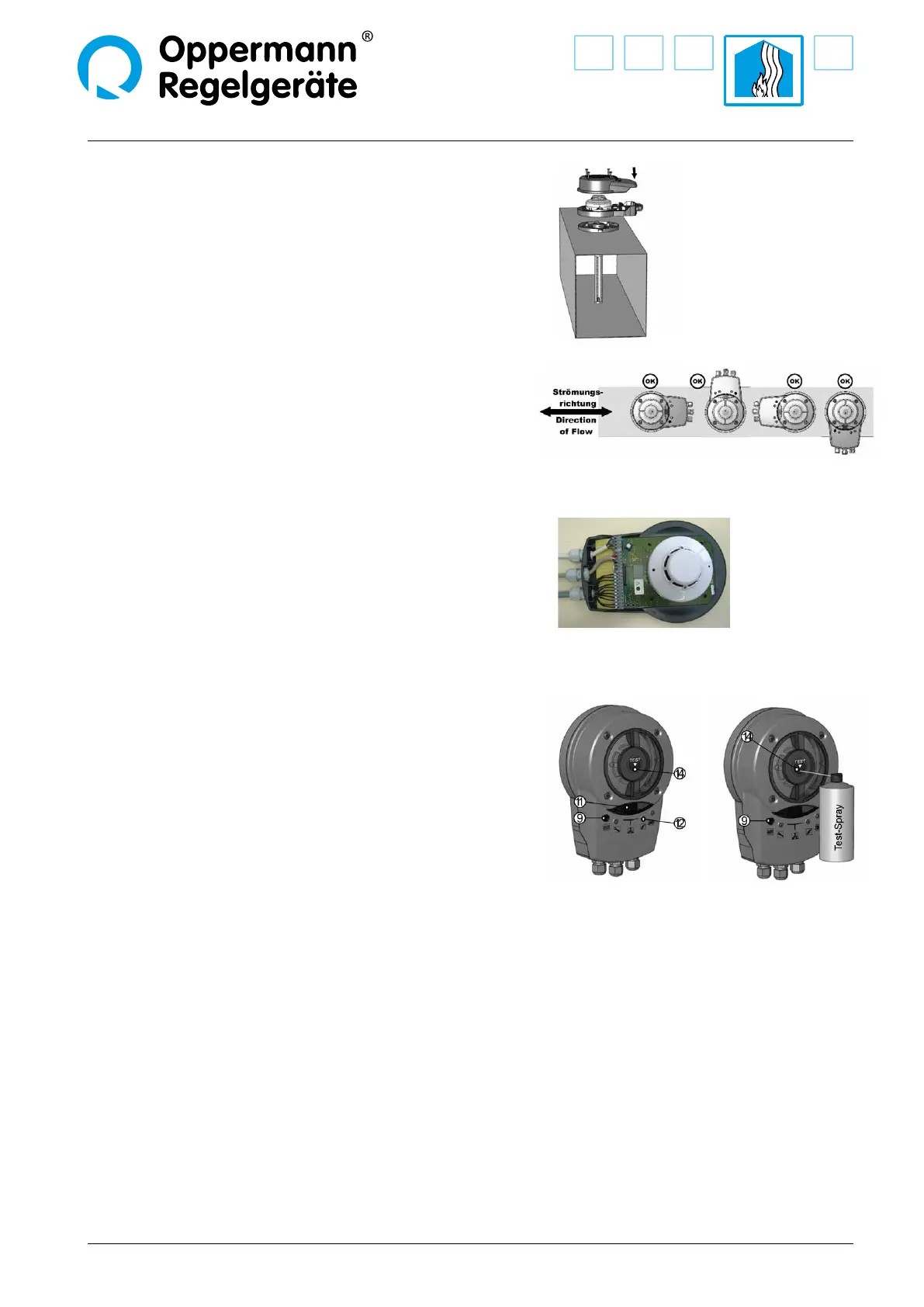
9. Testing the duct smoke sensor
• After completing the installation work, doing proper wiring (please
note the separate data sheets / circuit diagrams) and applying power,
the duct smoke sensor is operational.
• The green LED (12) illuminates.
• By pressing the alarm / reset button (9), an initial simple functional
test can be made. All LEDs must light up and all the relays drop out.
The units connected to the relays are activated! The display (11)
indicates the current degree of sensor contamination. If the button
is released, all LEDs will go out except for LED (12) which shows the
supply voltage, and the relays activate.
• For testing the smoke sensor the housing must not be opened. It has
a self-closing test opening (14) in the center of the transparent cover.
Use Oppermann test gas spray. Insert the test spray‘s tube fully into
the test opening (appx. 1.5 mm deep) and release as much test gas
as needed until the smoke sensor activates. Please do not spray too
much, otherwise the smoke sensor may display a higher degree of
contamination at the next start / reset. The alarm / reset button lights
up, the relays drop out. The electronics are on alert and locked. To
release, the alarm / reset button must be pressed. At the time of the
reset, the sensor must be free of smoke and test gas. Should there
still be test gas in the chamber a higher degree of contamination will
appear. In this case, after some time perform a reset by disconnecting
from the power or by an external reset, or if necessary, remove the
housing cover and blow out the smoke detector.
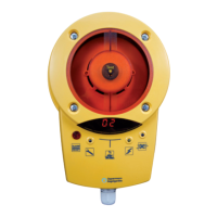
10. Final review
• Are all screws tight?
• Is the adapter plate properly mounted for the
ow direction?
• Are all seals in the correct position?
• In operation, when air ow > 1 m / s the blue
LED may not light up.
Application example:
 Loading...