Duct Smoke Detector KRM
2 | 9 | Fire Protection | Data sheet No. 41300 | Version 06-2012
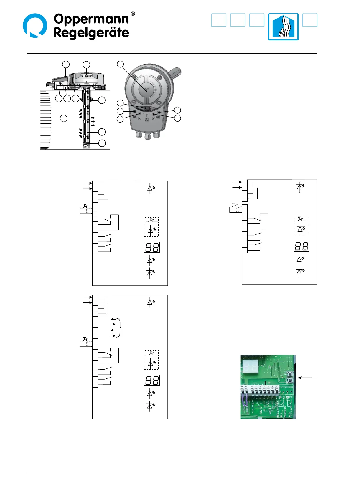
Power supply
230 V AC
Test/Reset
(NC contact)
Power supply
24 V AC / DC
Test/Reset
(NC contact)
Power supply
24 V AC / DC
Test/Reset
(NC contact)
Contact depictions are with
the power o (alarm)
KRM-2, 24 VKRM-1, 230 V
KRM-2-MOD, 24 V
9
10
11
12
13
14
15
green
16
17
yellow
blue
Smoke alarm
Smoke alarm
Service signal
Contamination
red
Test/Reset
3
4
Power supply
230 V AC
1
2
KRM-1
9
10
11
12
13
14
15
green
16
17
yellow
blue
Smoke alarm
Smoke alarm
Service signal
Contamination
red
Test/Reset
3
4
Power supply
230 V AC
1
2
KRM-2
Electrical connection
1
2
3
4
5
6
7
8
15
10
9
11
12
13
14
1 Adapter plate with gasket
2 Patented measuring tube (max. length 3 m)
3 End cap
4 Rubber bushing
(only for insulated or circular ducts)
5 Lower housing with seal
6 Electronics
7 Optical smoke sensor
8 Upper casing with seal
9 Red LED: alarm / reset button
10 Yellow LED: failure
11 LED display: % of sensor contamination
12 Green LED: in operation
13 Blue LED: air ow under 1 m / s
14 Opening for test gas
15 Air duct
Remote reset/test (terminal 9 +10): if bridge circuit is removed, a oating NC contact must be connected.
Notes: The oating switching contacts (terminals 11 – 17) are to be assigned as uniformly as possible to an installation category according
to EN 60730-1. These switching contacts are only to be used for 230 V AC or 24 V AC / DC, no combinations are permitted unless at least one
contact between the potentials remains unassigned. A mixed connection of safety extra-low voltage (SELV) and low voltage must not occur.
The assembly may only be operated on one mains phase. The voltage / safeguard activation is to be provided on site. KRM-1-xx
(230 V versions) with a fuse of 16 A; KRM-2-xx (24 V version) with 4 A.
9
10
11
12
13
14
15
green
16
17
yellow
blue
Smoke alarm
Bus B
Bus B
Bus A
Bus A
Smoke alarm
Service signal
Contamination
red
Test/Reset
3
4
5
6
7
8
Power supply
RS485 Modbus
(for information)
Power supply
24 V AC/DC
1
2
KRM-2-MOD
Programming the Bus address for the KRM-2-Mod:
Press buttons T3+T4 on the circuit board (to the right, next to the
display) at the same time, so that the display changes from con-
tamination level to show the bus address (the display will ash).
Press button T3 or T4 to adjust the desired address (1 – 99). The
last set bus address is automatically saved. The display resets auto-
matically after 3 seconds or by simultaneously pressing T3+T4.