Fire Protection | Data sheet No. 41300 | Version 06-2012 | 3 | 9
Duct Smoke Detector KRM
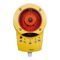
Display and operation for Duct Smoke Sensor KRM
LED Smoke alarm (red) LED Smoke alarm (red)
LED Failure (yellow) LED Power supply
(green)
LED Alarm (red) and
Alarm / reset button
Failure reset:
Briey press button and release
Alarm reset:
Press button for at least 2 seconds
until the red LED goes out
Display indicator
(contamination in % or status)
LED Air ow (blue)
lights up when there is insucient ow
Display Meaning Comments
Start / calibration
Shortly after starting the software version is displayed (4 digits),
e. g. 00 then 20 = Software 0020
Thereafter, the rotating segment display follows at startup or after a power failure.
00 – 99
Contamination
in %
Flashes starting at 70 %; at 99 % with display LED alarm.
Failure
e.g. Missing smoke detector, disrupted communication with the smoke detector,
processor failure.
Failure LED & alarm LED light up at the same time (not on the DIBt version).
Troubleshooting: Change the detector and conrm by pressing the alarm / reset button.
+
all LEDs on the
circuit board
light up
Conrmation
reset / new start
If alarm / reset button is pressed for more than 8 seconds, or if bridge circuit / terminal
9 / 10 is open (missing bridge circuit or remote reset). Display goes out after releasing the
alarm / reset button or closing the bridge circuit between terminal 9 + 10.
00 – 99
ashing
BUS address
Display only with MOD versions after pressing the address buttons T3 / T4 directly on the
circuit board.