OPTICAL SYSTEMS DESIGN
DOC ID: 10100110
OSD136 OPERATOR MANUAL
Page 5 of 16
1.2 TYPICAL CONFIGURATION
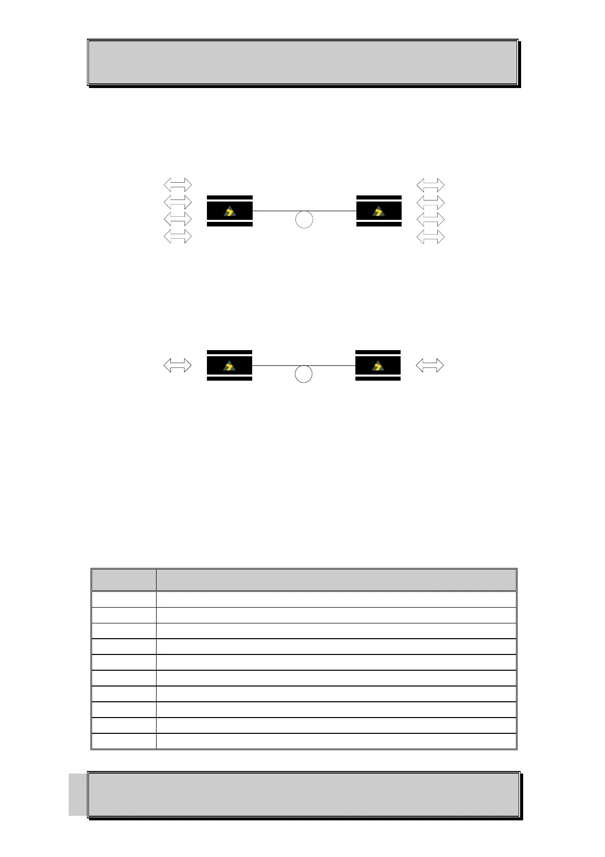
FIGURE 1 below shows a typical OSD136 link set up.
1 or 2 fibers
OSD136
Asynchronous
RS 232 x 4ch
OSD136
Asynchronous
RS 232 x 4ch
(a)
1 or 2 fibers
OSD136
Synchronous /
Asynchronous
RS 232 x 1ch
OSD136
Synchronous /
Asynchronous
RS 232 x 1ch
(b)
FIGURE 1: TYPICAL CONFIGURATION
(a) Multiplexed Asynchronous Configuration, (b) Synchronous Configuration
1.3 PRODUCT OPTIONS
There are various options available for the OSD136. These options are identified in TABLE 1 below:
TABLE 1: PRODUCT OPTIONS
ITEM DESCRIPTION
OSD136 Fiber Optic RS32 Transceiver, small module
OSD136L Singlemode Fiber Optic RS232 Transceiver, compact module
OSD136PP Plug pack for the OSD136
OSD136MB Wall mounting bracket for the small module
Option C Wall mountable module (for 1-fiber versions only)
Option /100 Card Version
Option WA Singlemode single fiber operation (Tx @ 1310nm, Rx @ 1550nm) (for option LC)
Option WB Singlemode single fiber operation (Tx @ 1550nm, Rx @1310nm) (for option LC)
Option WA Multimode single fiber operation (Tx @ 850nm, Rx @ 1310nm) (for option C)
Option WB Multimode single fiber operation (Tx @1310nm, Rx @ 850nm) (for option C)