OPTICAL SYSTEMS DESIGN
DOC ID: 10100110
OSD136 OPERATOR MANUAL
Page 7 of 16
1.5 PIN ASSIGNMENTS
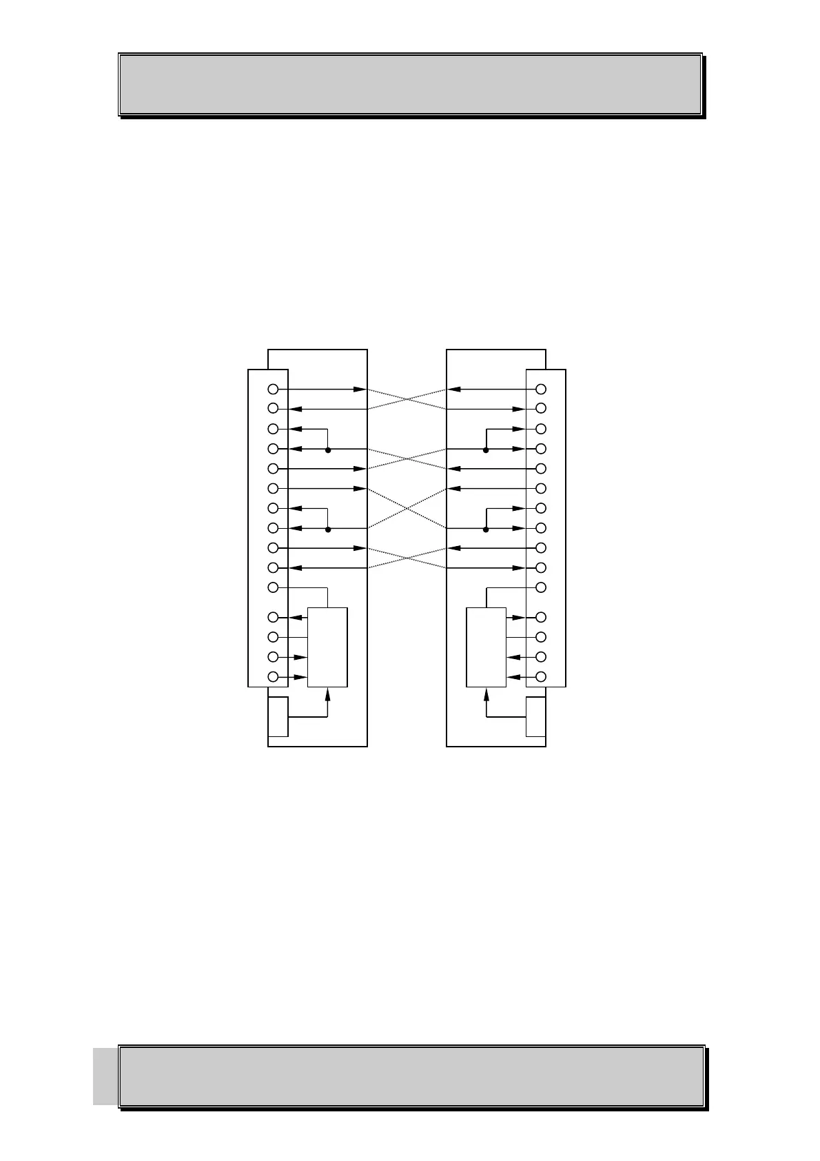
FIGURE 2 below identifies the pin assignments of the 25 pin D connector of the OSD136. The two
male D connectors represent two OSD136 modems that would be joined with a duplex fiber cable.
Shielded cables are recommended for all data wiring.
The + 8V to +13V external power shown is where the 1.3mm power plug would be attached if an
external OSD136PP power supply is used.
FIGURE 2 A) SYNCHRONOUS DATA TRANSFER
2
3
15
17
24
4
5
8
20
6
1
7
9
21
12
2
3
15
17
24
4
5
8
20
6
1
21
7
9
12
Tx DATA
Rx DATA
Tx CLK
Rx CLK
DTE Tx CLK
RTS
CTS
DCD
DTR
DSR
CASE GND
SIG QUAL
SIG GND
+9V POWER
+5V POWER
EXTERNAL
POWER 8-13V
Tx DATA
Rx DATA
Tx CLK
Rx CLK
DTE Tx CLK
RTS
CTS
DCD
DTR
DSR
CASE GND
SIG QUAL
SIG GND
+9V POWER
+5V POWER
EXTERNAL
POWER 8-13V
UP TO
SEVERAL KM
OF OPTICAL
CABLE
MALE D CONNECTOR
MALE D CONNECTOR