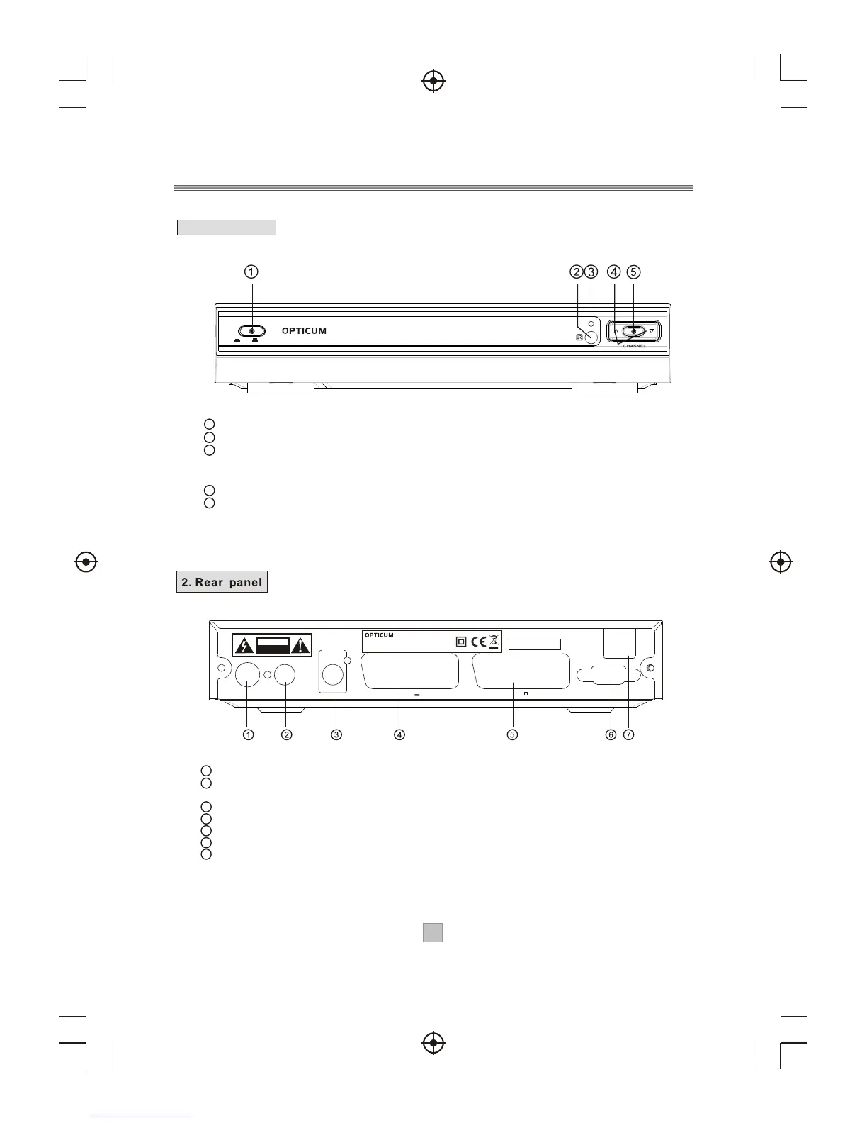
1 POWER BUTTON: Used to turn on or off of the main power of the unit.
2 REMOTE CONTROL SENSOR: Used to receive the signal from the remote control.
3 Standby Indicator: Used to visually show power state of the set top box, the green
LED will show if turned on the set top box and the red LED will be light if the set top box
entered standby mode.
4 CHANNEL UP/DOWN: Used to change channels without using the remote control.
5 STANDBY BUTTON: Used to switch the set top box on and off.
Front Panel and Rear Panel
1. Front panel
1 RF IN : This socket connects to your external aerial.
2 RF LOOP THROUGH: This socket will bypass the RF signal to either your TV or another
video system.
3 COAXIAL: This socket connects to a coaxial socket on your surround sound system.
4 VCR SCART: This socket connects to either a DVD or other video system.
5 TV SCART: This socket connects to your TV.
6 RS-232 PORT: This socket is only used for software upgrade.
7 MAINS CABLE: This is used to connect to your main power supply.
22
ON
OFF
7002T
Digital Terrestrial Receiver
LOOPLOOPRRFF
THROUGHTHROUGH
CoaxialCoaxial
Digital
Audio
Digital
Audio
VCR O OVCR O O
TVTV
SERVICE
Serial No.:
100-240V~
50/60Hz
DIGITAL TERRESTRIAL RECEIVER
POWER SUPPLY: 100-240V~ 50/60Hz
MAX POWER CONSUMPTION: 10WATTS
MODEL: OPTICUM 7002T
ININRR FF
RISK OF ELECTRIC SHOCK
DO NOT OPEN COVER
CAUTION