1660-IN-010-0-04 Page 3
5.481
0.075
1.423
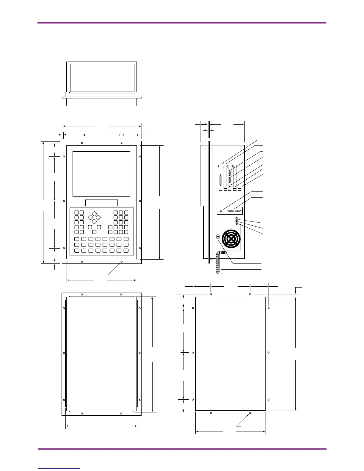
Figure 1. Model DSA2 Dimensions for Flange Mount
Remove cover for access to
expansion slots.
Parallel port
PCI expansion slot
Serial port (COM1)
CRT port
Internal keyboard
ISA expansion slot
ISA expansion slot
External keyboard (mini-DIN)
Interbus-S In (pins)
Interbus-S Out (sockets)
for machine function keys
Chassis Ground
DC - (0 Vdc)
DC + (24 Vdc)
Power Switch
12.620
5.000.375
1.873
7.483
19.462
7.483
1.873
.375
3.435
Ø .218 (10)
17.844
11.000
5.0003.435
1.873
7.483
0.310
7.483
1.873
3.435
Ø .218 (10)
18.092
11.250
17.992
11.150
Bond Strap
24 Vdc
Class 2 Input
Include a switch or circuit breaker in the installation. It must be placed in close proximity to the equipment,
within easy reach of the operator and must be marked as the disconnecting device for the equipment.