1660-IN-010-0-04 Page 5
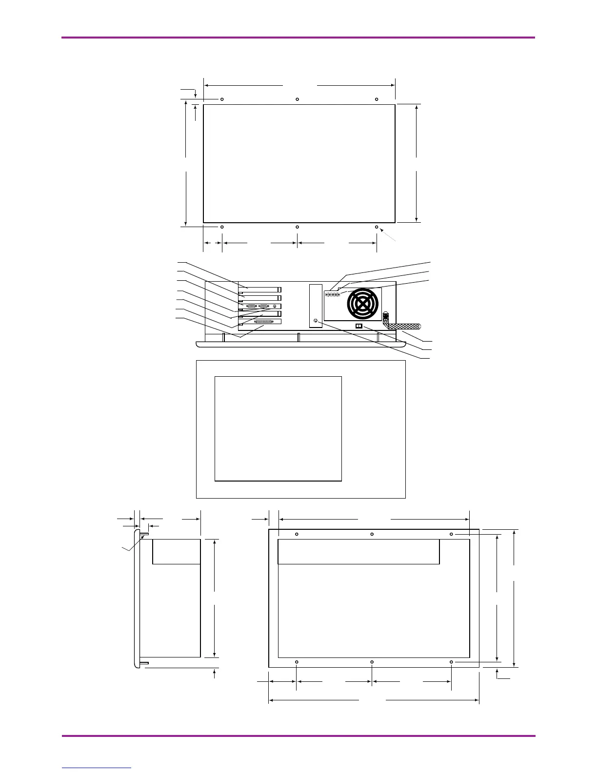
Figure 3. Model DSB2 Dimensions for Flange Mount
17.842
19.400
.455
2.200
.779
7.500 7.500
11.640
12.550
11.000
.775
6.575.375
.675
#8 - 32 Thread
(6 places)
18.100
11.640 11.280
7.500
.180
Ø .188 (6)
7.5001.550
ISA expansion slot
ISA expansion slot
Serial port (COM1)
CRT port
Internal keyboard
PCI expansion slot
Parallel port
Chassis Ground
DC - (0 Vdc)
DC + (24 Vdc)
Bond Strap
Power Switch
External keyboard (mini-DIN)
24 Vdc
Class 2 Input
Include a switch or circuit breaker in the installation. It must be placed in close proximity to the equipment,
within easy reach of the operator and must be marked as the disconnecting device for the equipment.
Note that this panel cutout
applies to both the
Model DSB2 and
the Remote I/O Station