6
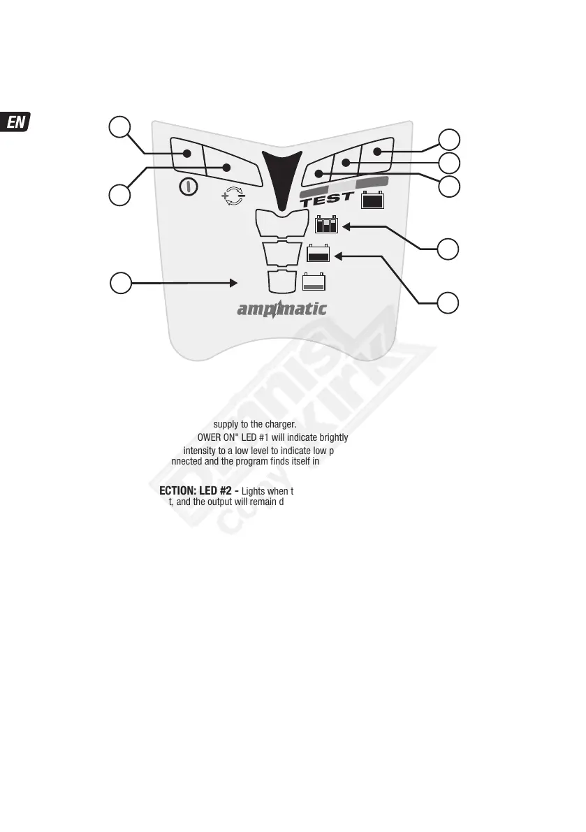
PROCEEDING TO CHARGE
The LED indicators below are sequenced as they may come on through the course of the program.
POWER ON: LED #1 - Confirms AC power supply to the charger.
HIGH and LOW intensity indication: The"POWER ON" LED #1 will indicate brightly when current is delivered to the battery.
The "POWER ON" LED #1 will reduce intensity to a low level to indicate low power "ECO" mode. This will occur if there is no battery
connected, or when a battery is connected and the program finds itself in the voltage retention test mode or the 'rest' periods of
Maintenance Charge mode.
REVERSE POLARITY PROTECTION: LED #2 - Lights when the battery connections are incorrect. The charger is electronically
protected so no damage will result, and the output will remain disabled until the connections are corrected.
2
1
8
7
6
5
4
3
C:100-240V
EVERSE
OLARITY
ONNECTION
TEST +
MAINTAIN
OPTIMIZE
CHARGE
SAVE
SAVE
safeTº
CHARGE
OPTIMIZE