OPTIMUM
MASCHINEN - GERMANY
Description of the connection
29 / 11 / 2006
Page
5
Description of the connection CNC Controller III and VI ; Version 2.0.1
© 2006
GB
5 Connections
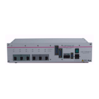
5.1 CNC Controller III
Fig.5-1: Connection to the CNC controller III
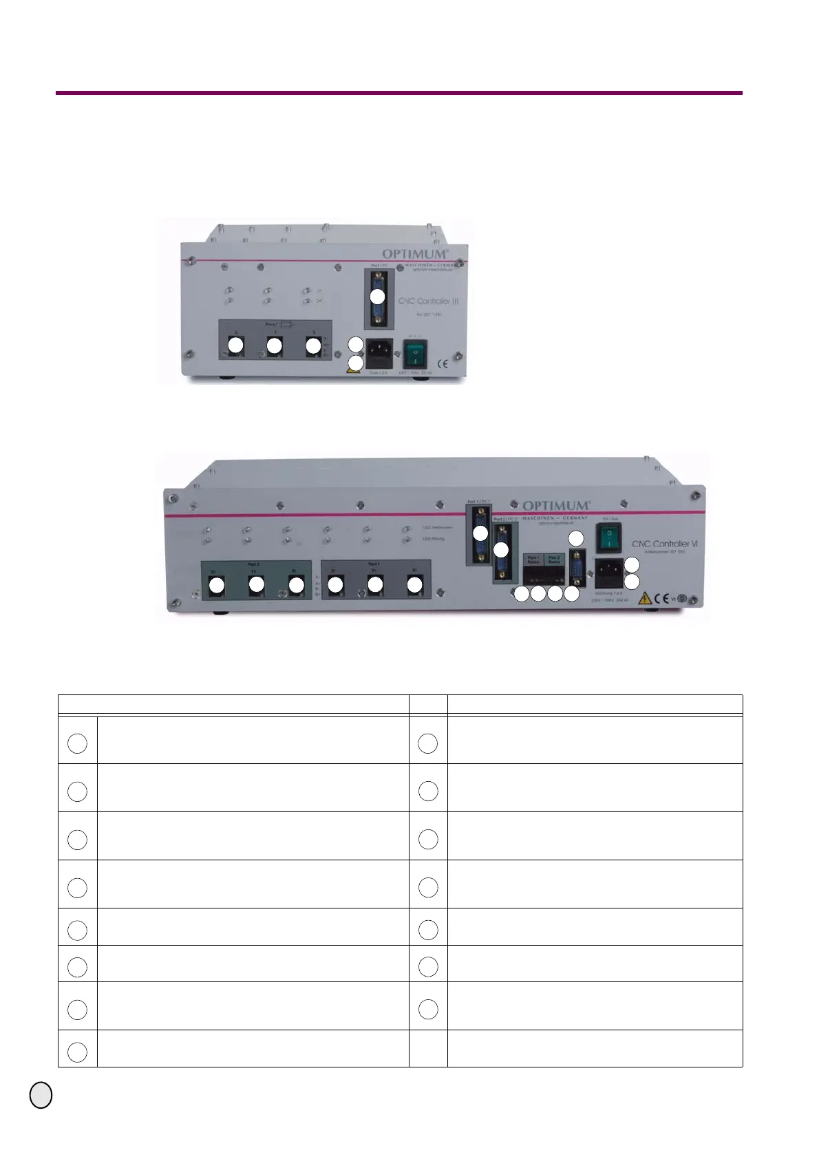
5.2 CNC Controller VI
Fig.5-2: Connection to the CNC controller VI
6 Description of the connection
1
3
7
2
13
14
2
3
4
5
6
1
7
8
9
10
12
11
14
13
15
Description Description
Z
1
connection step motor Z - axis of the machine
Port 1 relay potential-free relay output, for user-
defined application in connection with Port 1 / PC1,
maximum 10 A
Y
1
connection step motor Y - axis of the machine
Port 1 relay potential-free relay output, for user-
defined application in connection with Port 1 / PC1,
maximum 10 A
X
1
connection step motor X - axis of the machine
Port 2 relay potential-free relay output, for user
defined application in connection with Port 2 / PC2,
maximum 10 A
Z
2
connection step motor Z
2
- axis of the machine
Port 2 relay potential-free relay output, for user
defined application in connection with Port 2 / PC2,
maximum 10 A
Y
2
connection step motor Y
2
- axis of the machine
mains supply
X
2
connection step motor X
2
- axis of the machine
Fine-wire fuse 1.6 A slow-blow
Port 1 / PC1 parallel port, LPT connection of the per-
sonal computer to the control of the axis Z, Y, X
Connection reference switch (ref.switch) to con-
nect the optionally available reference switch for
the machine point of origin.
Port 2 / PC2 parallel port, LPT connection of the per-
sonal computer to the control of the axis Z
2
, Y
2
, X
2
1 9
2
10
3
11
4
12
5
13
6
14
7
15
8