OPTIMUM
MASCHINEN - GERMANY
Description of the connection
29 / 11 / 2006
Page
7
Description of the connection CNC Controller III and VI ; Version 2.0.1
© 2006
GB
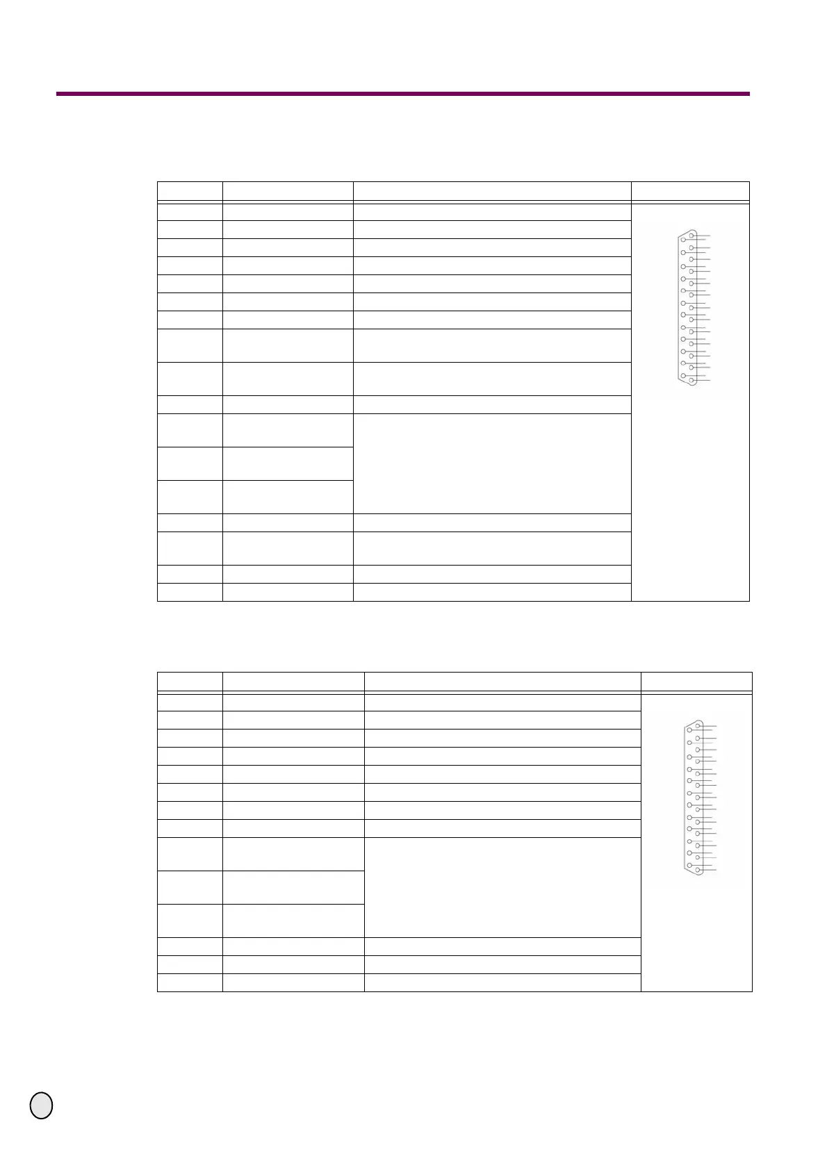
6.1.3 Assignment of signals at the parallel port 1, CNC controller VI (port / PC)
The following assignment of signals is required at the parallel port 1.
6.1.4 Assignment of signals at the parallel port 2, CNC controller VI (port / PC)
The following assignment of signals is required at the parallel port 2.
Pin No Application Description DB 25 male
1 Relay 9 Switching output e.g. motor on
2 Direction X-axis Direction signal to control the axis
3 Cycle X Cycle signal to control the step motor
4 Direction Y Direction signal to control the axis
5 Cycle Y Cycle signal to control the step motor
6 Direction Z Direction signal to control the axis
7 Cycle Z Cycle signal to control the step motor
8 Direction 4th axis
Direction signal of the optional 4th axis
“Optional 4th axis on parallel port 1“ on page 8
9 Cycle 4th axis
Cycle signal of the optional 4th axis
“Optio-
nal 4th axis on parallel port 1“ on page 8
10 Free Not assigned
11
Reference switch Z
axis
“Assignment of signals at the port refe-
rence switch (Ref.switch)“ on page 6
12
Reference switch Y
axis
13
Reference switch X
axis
14 Relay 10 Switching output e.g. coolant on
15
Reference switch 4th
axis
16 - 24 Free Not assigned
25 OV DC, earthing
2
3
4
5
6
7
8
9
10
11
12
13
14
15
16
17
18
19
20
21
22
23
24
25
1
Pin No Application Description DB 25 male
1 Relay 11 Switching output e.g. motor on
2 Direction X - axis Direction signal to control the axis
3 Cycle X Cycle signal to control the step motor
4 Direction Y Direction signal to control the axis
5 Cycle Y Cycle signal to control the step motor
6 Direction Z Direction signal to control the axis
7 Cycle Z Cycle signal to control the step motor
8 - 10 Free Not assigned
11
Reference switch Z
axis
“Assignment of signals at the port refe-
rence switch (Ref.switch)“ on page 6
12
Reference switch Y
axis
13
Reference switch X
axis
14 Relais 12 Switching output e.g. coolant on
15 - 24 Free Not assigned
25 OV DC, earthing
2
3
4
5
6
7
8
9
10
11
12
13
14
15
16
17
18
19
20
21
22
23
24
25
1