Do you have a question about the Optimum OPTI turn TU 3008G and is the answer not in the manual?
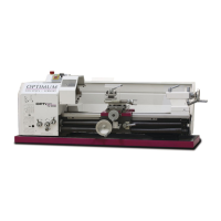
Specifies the model and identification number of the lathe.
Information about the machine's specifications and manufacturer as shown on the rating plate.
Explanation of hazard classifications, warning notes, and safety symbols used.
Defines the proper and intended application of the lathe.
Details potential misuses of the lathe and outlines inherent risks associated with operation.
Specifies required user qualifications and responsibilities for safe operation.
Precautions to take during the operation of the lathe.
Lists and explains the safety features integrated into the lathe for protection.
Procedures for regularly checking safety devices and performing maintenance.
Recommended PPE for safe operation and maintenance of the lathe.
Steps for safely disconnecting and securing the lathe for maintenance.
Recommendations for checking and maintaining electrical components.
Details on the lathe's electrical power requirements and drive motor specifications.
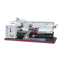
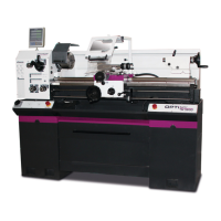
Dimensions defining the lathe's working capacities and headstock details.
Tables showing longitudinal/cross feed rates and thread pitches.
Specifications for the lathe's slides, tailstock, and overall dimensions.
Suitable operating conditions and recommended lubricants for the lathe.
Information on sound pressure levels emitted by the machine.
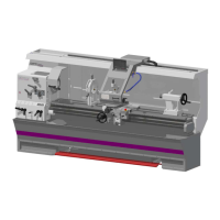
General guidelines and precautions for handling the machine during transport and installation.
Critical information on safe lifting points, procedures, and forklift usage.
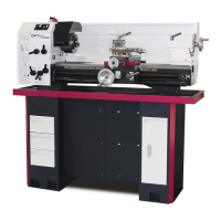
Diagrams showing the center of gravity for the lathe, with and without base.
Requirements for the installation environment to ensure optimal functionality.
Instructions for cleaning the lathe and details on initial lubrication.
Steps and precautions for the initial startup of the lathe.
Guidelines for connecting the lathe to power and warming it up.
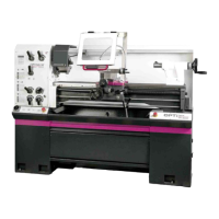
Identification and explanation of the lathe's controls and indicators.
Essential safety conditions and checks for operating the lathe.
Procedures for safely starting, stopping, and resetting the lathe.
How to adjust spindle speed, feed rate, and change gears.
Procedures for clamping workpieces, adjusting fixtures, and replacing chuck jaws.
Methods and calculations for turning tapered workpieces.
Recommended cutting speeds, data, terms, and tool geometry.
Methods for tapping external and internal threads and thread types.
General guidelines for operating the lathe, including clamping long workpieces.
Functions and cross-adjustment procedures of the tailstock.
Information on cooling lubricants and detailed specifications for the rotary chuck.
Safety guidelines, basic instructions, and force calculations for the rotary chuck.
Safety precautions during maintenance and repair work, including preparation and restarting.
Schedule and procedures for routine checks, lubrication, and oil changes.
Information on how to request repair services from customer technicians.
Information required for ordering parts and contact details for support.
Illustrated diagrams and detailed lists of spare parts for various machine assemblies.
Electrical wiring diagram for a single-channel configuration.
Electrical wiring diagram for a double-channel configuration.
Copyright notice and definitions of technical terms used in the manual.
Information regarding warranty terms, limitations, and exclusions.
Guidelines for proper storage and procedures for safe dismantling and transport.
Procedures for decommissioning, disposal of packaging, lubricants, and components.
Information for product follow-up and a log of manual changes.
Measurements of spindle run-out and parallelism for precision.
Measurements of tailstock and chuck alignment for accuracy.
| Swing over bed | 300 mm |
|---|---|
| Distance between centers | 800 mm |
| Spindle bore | 38 mm |
| Spindle speed range | 125 – 2000 min⁻¹ |
| Motor power | 1.5 kW / 230 V |