M130 Version 1.0 Page 8 of 23
M130
8x8 Audio Matrix
7. Input connectors for the remote controls M134P and M134T.
You can connect to each zone output a remote control (either a M134P or M134T). By a DIP
switch, you will have to assign an address to each remote control.
Each remote control has to communicate with the zone that has been assigned. Do not give
the same address more than one remote control.
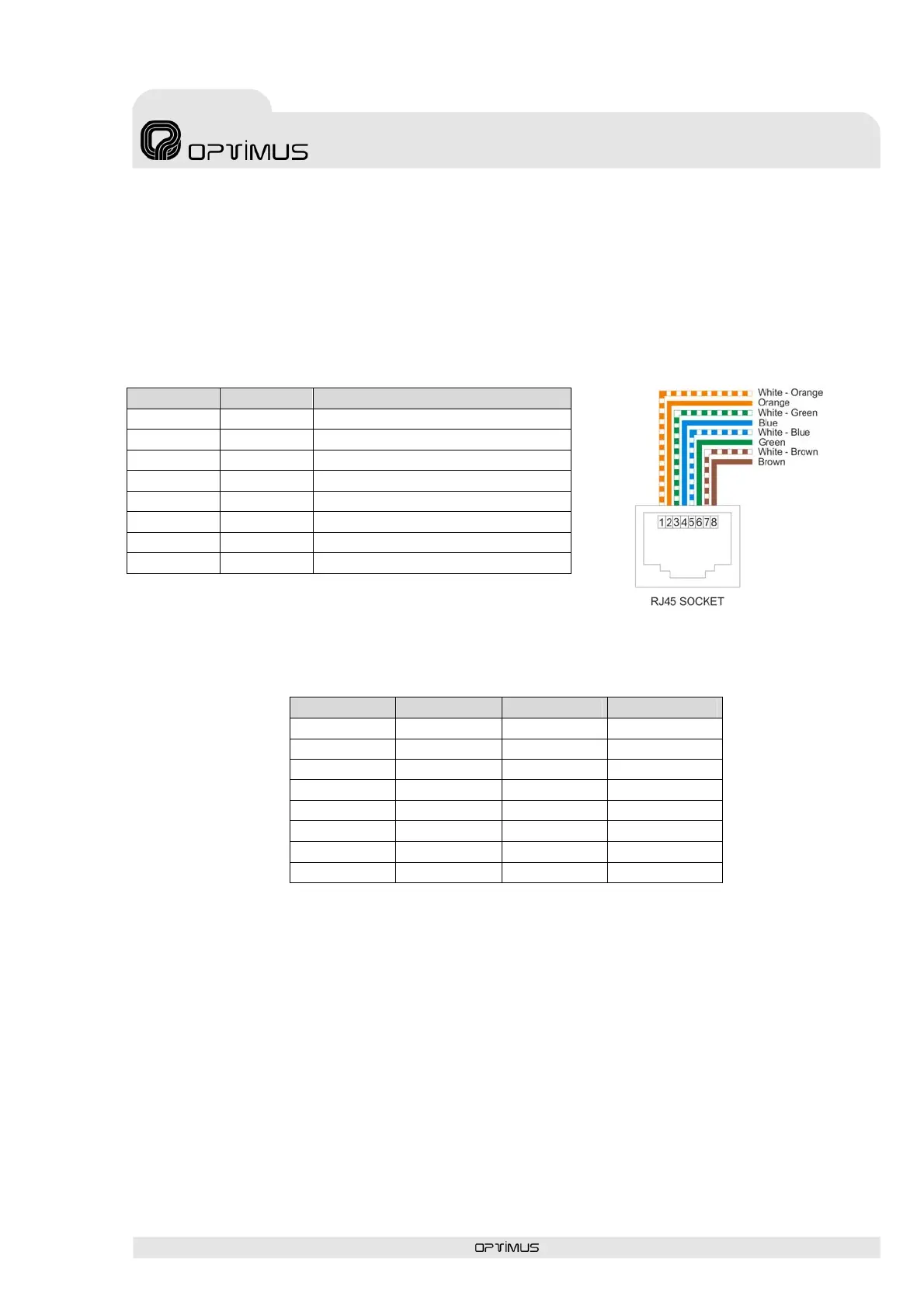
The connector Pin description of the remote control M134P and M134T (RJ45 CAT5 UTP) is
as follows:
PIN Nº Name Description
1 Tx+ Positive transmission RS-422
2 Tx- Negative transmission RS-422
3 Rx- Negative reception RS-422
4 DC output +24VDC power
5 GND Digital ground
6 Rx+ Positive reception RS-422
7 Audio + Balanced audio positive
8 Audio - Balanced audio negative
Follow the table below to configure the address of the remote controls M134P and M134T:
DIP switch 1 DIP switch 2 DIP switch 3 Zones
OFF OFF OFF Zone 1
ON OFF OFF Zone 2
OFF ON OFF Zone 3
ON ON OFF Zone 4
OFF OFF ON Zone 5
ON OFF ON Zone 6
OFF ON ON Zone 7
ON ON ON Zone 8
8. Connectors for the remote microphone station M132M.
You can connect up to four remote M132M microphones to the M130 matrix. The address of
each M132M must be set properly.
To connect the M132M microphone, you must use CAT5 STP cable. (We recommend shielded
of 8 twisted pairs).
When you use a cable 8 pair unshielded twisted CAT5 UTP, don't connect the PIN6 (A-GND).
The M132M also works, but has less ability to suppress interference.
 Loading...