OP175 System Installation, Operation & Maintenance 11
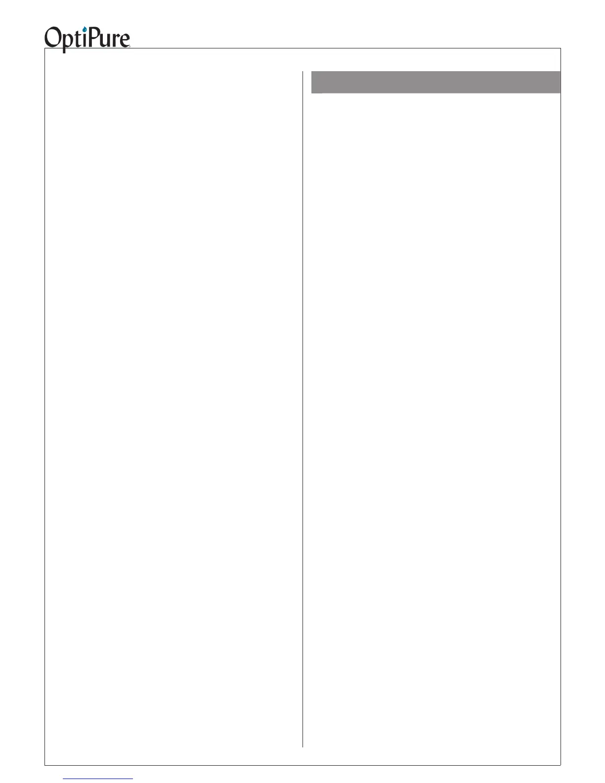
• The Repressurization Pump (15) is designed
to draw water from the Atmospheric Storage
Tank (14) and dispense the Optimized water
to the Processor and through the One-Way
Check Valve (5) and out to the equipment.
A Buffer Tank (18) between the pump and
the downstream equipment to prevent short
cycling of the pump for low volume demands.
The Repressurization Pump is equipped with
a pressure switch so that when the pressure
in the Buffer Tank drops, the Pump runs to
repressurize the Buffer Tank, and when the
pressure reaches 70 psi, the Pump shuts off.
• Water demand for downstream equipment is
directly supplied from the Buffer Tank (18),
and demand can go on and off as necessary.
The RP Pump is not directly affected by
downstream demand, but only activates in
response to a sufcient drop in Buffer Tank
pressure. Downstream equipment is also not
affected by the automatic starting or stopping
of the RP Pump.
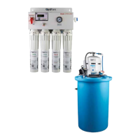
• The Optional Post-Treatment Filter (20) is
designed to provide additional treatment
based upon specic application requirements.
For beverage applications an activated
carbon lter is recommended.
• As Optimized Water is dispensed from the
storage tank by the Repressurization Pump
(15), air is replaced in the tank through the
Sub-Micron (0.2 micron) Air Breather (16).
• If the Repressurization Pump (15) fails, water
ow and can be restored to the equipment by
turning the Emergency Bypass Valve (3) to
the position to “SYSTEM BYPASS” position.
This allows tap water to bypass the processor
and RP assembly.
• A Sample Port (13) provides the ability to
measure membrane production by closing
the Buffer Tank Valve (17) and turning the
Tank Inlet Divert Valve (11) to the bypass
or UP position. This diverts the permeate
(pure water produced by membrane) from the
Storage Tank (14) through the Bypass Check
Valve (19) and back to the processor where
opening the Sample Port (13) will allow you to
directly measure the permeate ow rate.
• Additionally the Sample Port (13) provides
the ability to drain water from the Storage
Tank (14) by closing the user-supplied Water
Supply Valve, opening the Buffer Tank Valve
(17) and opening the Sample Port (13).
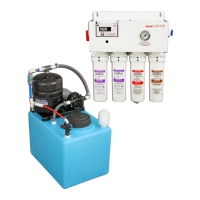
Repressurization Pump
The Repressurization Pump Assembly that comes
standard with the OP175 System includes a
diaphragm pump controlled by a built-in Pressure
Switch, and a Buffer Tank between the Pump and
the downstream equipment maintains pressure
downstream. When a valve or solenoid valve is
opened down-stream of the Buffer Tank, the de-
mand is supplied from the Buffer Tank. When the
pressure drops sufciently in the Buffer Tank, the
pump starts automatically and rells the Buffer
Tank. The operating pressure for the Buffer Tank
is preset (to 70 psi) and is NOT eld adjustable.
The pump also incorporates check valves to keep
the Buffer Tank and downstream line pressurized.
The pump is equipped with auto-reset, thermal
overload protection and is designed for intermit-
tent duty.
If the pump runs erratically, allow the pump
to run to open drain with valve fully open to
purge air from the pump head. Disconnect the
power and reconnect several times to facili-
tate air purging.
Pump will prime only if all the pressure is relieved
from the outlet port. The pump is self-priming up
to 11 ft. The pump can run dry but will overheat
and the pump overload will shut the pump off.