A
Alan EdwardsAug 19, 2025
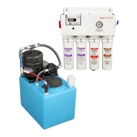
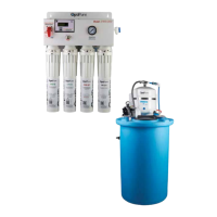
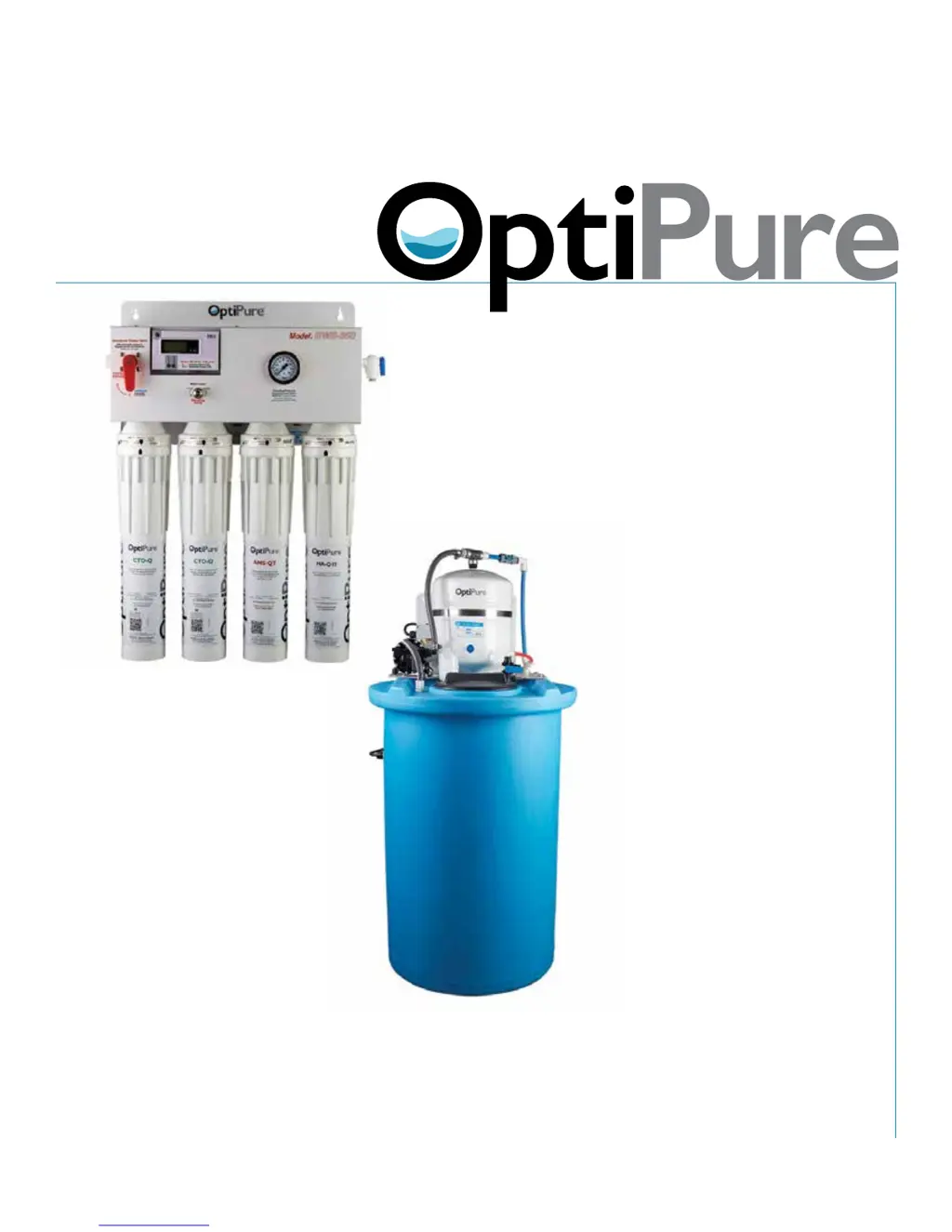
What to do if the OptiPure BWS350 Water Filtration Systems RP Pump does not turn on?
- RRyan JohnstonSep 12, 2025
If the green LED is off, ensure the power cord is plugged into a working outlet and that there is water in the tank. Check the circuit breaker. If the LED still doesn't turn on with power and water in the tank, there may be an issue with the Low Level Float Switch or Relay. Allow the Processor to partially fill the tank. If bumping the RP Pump yields no response, the pump could be damaged, or the brushes may still be worn; in this case call for service. If the LED is on, the RP Pump is operational and will only activate when the Buffer Tank is empty. Try tapping the RP Pump; if it temporarily starts, the brushes are likely worn and need replacement with Brush Kit 704-39905.