BWS350 System Installation, Operation & Maintenance 3
The BWS350 Advanced Membrane Separation System is designed specically for users that desire the ability to customize
the TDS (Total Dissolved Solids) level or “Mineral Content” of the treated water. The BWS350 utilizes a precision multi-turn
Blending Valve to accomplish this with great accuracy. This system design maximizes the ability to accurately blend a calcu-
lated percentage of the ltered water with the product water exiting the AMS-QT Membrane, providing an Optimized Water to
your equipment with the characteristics that you desire.
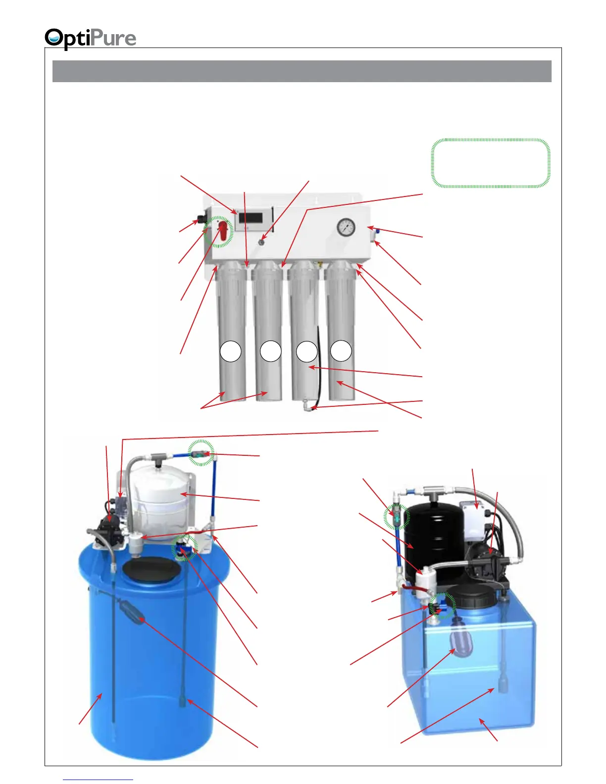
Getting To Know Your System
Feed Water Inlet
3/8” Push-To-Connect -
Connect to Water Supply Valve.
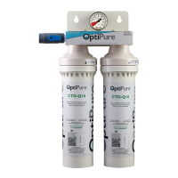
CTO-Q (2x)
Pre-Filters
Water Quality Indicator - Operates
momentarily, push purple button to turn on.
Push “IN” button for the TDS of the water
going into your equipment. Push “OUT”
button for the TDS of the puried water from
the membrane.
Emergency Bypass Valve -
User can switch from Optimized
Water to Untreated Water
when needed, by turning handle
horizontal.
Optimized Water To
Storage Tank - 3/8” Push-To-
Connect - Connect to Optimized
Water Storage Tank Inlet
Membrane Reject Water
Tubing Connection
AMS-QT Membrane
Cartridge
Reject Water Outlet - 1/4”
Push-to-Connect - Connect to drain
per local regulations.
1
2
3
Tank
Repressurization Return-
1/2” gray hose - Connect to
Repressurization Assembly Outlet
Pressurized
Optimized Water Outlet -
1/2” gray hose
-Connect to End User Equipment
Sample Port -
3/8” Push-to-Connect - Used to ush pre
lters, gather a water sample, measure pro-
duction, or drain water from storage tank.
Blending Valve - Allows
precise adjustment of optimized
water TDS (mineral content).
120VAC or 230VAC Power Cord
- Plug in to standard wall outlet.
Reject Flow Control Valve
Operating Pressure Gauge
Shows feed pressure only when processor is
operating (when level in storage tank is low).
Normal
Operation
Items in green circles show a nor-
mal operating condition/position.
Optimized Water to Storage Tank
Inlet (on Valve)
- 3/8” Push-to-Connect - Connect to Opti-
mized Water Outlet on Processor.
Absolute 0.2 micron
Hydrophobic Air-Breather/Filter
Repressurization Assembly
Outlet - 1/2” Hose Barb - Connect to
Pressurized Water Inlet on Processor
Repressurization
Pump
120VAC or 230VAC -
Plug in to
standard wall
outlet
Repressurization
Pump
Buffer Tank
- Pre-charged air bladder - 20 psi
Optimized Water Storage Tank
- 16 gal. Atmospheric
Optimized
Water
Storage Tank
- 50 gal. Atmospheric
Buffer Tank Valve
- Normally open (handle parallel to
valve body). Used to shut off water
supply to downstream equipment.
High Level Float Switch (in Tank)
& Cable (on back or side of tank) - Connect
Cable to Processor “Tank Electrical Connection.”
Tank Inlet Divert Valve
- Normally in Down position. Turn handle to Up
position to divert Optimized water to sample port.
Low Level Float Switch (in Tank)
- Shuts off pump (using Relay) when tank is empty.
Low Level Relay & Control Box -
120VAC or
230VAC
- Plug in cord to standard wall outlet. Box
connected to LL Float Switch & Pump. Light on top
illuminates when there is water in tank & Pump is enabled.
4
MA-Q15 Mineral
Cartridge