BWS350 System Installation, Operation & Maintenance 7
Wall Mounting
The processor should always be mounted where it
is well-supported, either using anchors in a cement
wall, or using the support of studs in a wall-board
wall. Never mount it directly to sheet-rock alone.
Instead, mount it on a sheet of plywood which is
anchored to the wall studs, as shown above.
Four user-supplied bolts or screws with a head
diameter of approximately 1/2” (which will t into the
keyholes in the system bracket, but will not slip out
when tightened) should be used to hang the system.
This will allow the unit to be lifted off the bolts, if
necessary for maintenance, without removing all
the bolts from the wall. Hold the processor in place
(without the cartridges) to mark the locations
for the screws. BE SURE TO ALLOW 3”
BELOW THE CARTRIDGES TO ALLOW FOR
REMOVAL. Screw the four bolts or screws in
place, leaving approximately 1/4” clearance
between the bottom of each bolt head and the
wall. Position the system over the mounting
bolts, and let the bracket slip down into the
keyholes. Tighten all screws.
System Installation
Note: Do not install the cartridges in the
processor until completing this section.
Do not plug in the power cord from the RP
pump until completing the following section,
“System Start-Up”.
Refer to “Typical Installation” diagram on
page 6 and “How to Use Our Quick-Connect
Fittings” on page 20 when making the
following connections.
A feed water ball valve and pressure gauge (user
supplied) should be installed to provide water to
the system FEED WATER INLET with the green
tubing (supplied). Hose, tubing and ttings for
making connections between the processor,
storage tank and drain are supplied in the
installation kit.
1. Remove the tank lid. Inside the tank, the oat
valve may be secured for shipping. Remove
any wrapping on the oat to allow it to hang
and move freely.
2. DRAIN: Connect the 1/4” black tubing from
the installation kit to the REJECT WATER
OUTLET on the processor. Run the line to
an appropriate drain. Observe local plumbing
codes and supply an appropriate air gap.
(Any ttings for connecting to the drain will
need to be supplied by the customer.) Fix
tubing in place at the drain.
3. FEED WATER: Apply 3 ‘wraps’ of Teon tape
to the 1/2” FPT x 3/8” push-connect tting
(supplied). Screw the tting into the Feed
Water Supply Ball Valve and tighten (DO
NOT OVERTIGHTEN). Connect one end
of the 3/8” GREEN TUBING to this tting.
Connect the other end of the tubing to the
FEED WATER INLET located on the left
side of the Processor. Cut the tubing to the
required length if necessary.
Plywood anchored to wall
10.5”
14.7”
8.9”
12.7”
Outside edge of
processor bracket
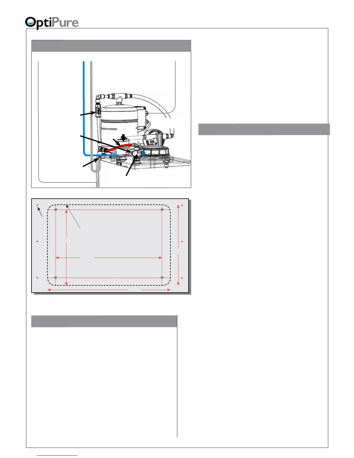
Installation with 16 Gal. Storage Tank
Optimized Water
Line
- Connect to
Processor Optimized
Water Outlet
Optimized
Water to
Storage Tank Inlet
(on Valve)
Repressurization
Assembly Outlet
(Hose Barb)
Repressurization
Pump
Buffer Tank
Buffer Tank
Valve
(Normally Open)
Optimized Water
Storage Tank
- 16 gal. Atmospheric
Tank Inlet
Divert Valve
Refer also to “Typical Installation” Diagram on previous page.
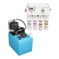
Power Cord
-to
120VAC or 230VAC
Outlet
Pressurized
Water Line
- connect to
Processor Tank
Repressurization
Return
High Level Switch Cable
-Connect to electrical box on
left side of Processor
Bypass
Air
Breather