BWS350 System Installation, Operation & Maintenance 9
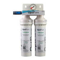
Install QT Cartridges
NOTE: Before installing the QT Cartridges, make sure
to remove the four plugs in the QT heads.
1. Insert the CTO-Q cartridges into QT heads 1 & 2
(starting from the left or inlet side of the processor)
and turn to align arrows.
2. Insert the AMS-QT membrane cartridge into the
QT head #3 and turn to align arrows.
3. Insert the MA-Q15 mineral cartridge into QT head
#4 and turn to align arrows.
4. Connect the Push-to-Connect elbow (remove plug
in elbow) on the end of the black Reject tubing to
the stem connector on the bottom of the AMS-QT
cartridge.
System Start-Up
Refer to illustrations “Typical Installation” (page 6) and
“High Level Switch Testing” (page 20).
IMPORTANT: Before proceeding, position the
Processor EMERGENCY BYPASS VALVE in the
“SERVICE” position, assure that the BUFFER TANK
VALVE is open, and position the TANK INLET DIVERT
VALVE in the down position (Blue Valve Handle
pointing sideways).
1. Slowly open the user-supplied WATER SUPPLY
VALVE. Plug the processor power cord into a
120VAC outlet. Allow the lter housings to ll, and
water will begin to ow from the end of the 1/4”
black tubing routed to the drain. After some time,
water will begin to ow into the tank. Allow several
minutes to ush the system until water ows
smoothly into the tank and also from the drain line.
Check all of the plumbing connections and correct
any leaks if necessary.
2. Test the high level oat switch. With the tank lid
removed and the system running, raise and tilt the
high level oat (in the tank). As you raise the oat
upward, the ball inside the oat will roll from one
end of the oat to the other, activating the switch.
• With the oat in the upright position, the water
processor should shut off the water ow.
• Lower the oat allowing the ball to drop back
down. The water should begin owing again.
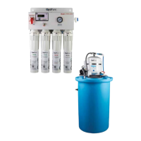
3. The 16 Gal Storage Tank must be lled - or the 50
Gal Storage Tank lled approximately 1/3 of the
way - to start-up and purge the Repressurization
Assembly. You can quickly ll the storage tank
to the appropriate level using the “System
Bypass” on the processor. To do this:
• Route the 1/2” gray hose from the processor
OPTIMIZED WATER OUTLET TO EQUIPMENT
directly into the storage tank lid opening.
NOTE: Before performing the next step, be certain
to hold onto the gray hose.
• Turn the EMERGENCY BYPASS VALVE on the
processor to the “BYPASS” position. This will
allow feed water to bypass the processor and
quickly ll the storage tank.
• When the tank lls to approximately 14
gallons (or 1/3 full with the 50 gal. tank),
return the PROCESSOR EMERGENCY
BYPASS VALVE to the “SERVICE” position.
NOTE: Before performing the next step, be certain
to hold onto the gray hose.
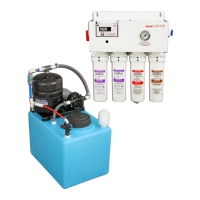
4. Plug the power cord from the RP pump into the
outlet. Water should begin to ow rapidly from
the storage tank, through the RP assembly,
and back into the storage tank through the gray
hose. Allow the pump to recirculate the water for
several minutes until all the air is purged from the
Repressurization Assembly. As the air is purged,
the pump will begin to run more smoothly and
the water owing from the gray hose will become
steady.
5. Unplug the RP Pump cord.
Connect to Equipment
Refer to the illustration “Typical Installation” on page 6.
1. Remove the 1/2” gray hose that was routed
into the storage tank (from the Optimized Water
Outlet at the Processor) and make the connection
to the distribution line that delivers Optimized
Water to post-treatment (if used) and designated
equipment.
2. Ensure that any valves or solenoid valves on the
connected equipment are closed. Plug the RP
Pump back in. The pump will run and ll the Buffer
Tank until the pressure in the Buffer Tank reaches
70 psi, and then the RP Pump will shut off.
 Loading...