BWS350 System Installation, Operation & Maintenance 8
NOTE: When cutting the tubing use a sharp tubing
cutter or blade and make a clean, straight cut
before inserting into a push-connect tting. When
routing tubing, do not make sharp bends or crimp
the tubing.
4. PROCESSOR TO TANK: Connect a piece of
the 3/8” blue tubing to the OPTIMIZED WATER
TO STORAGE TANK tting on the processing
unit. Connect the other end of this tubing to the
OPTIMIZED WATER TO STORAGE TANK INLET
on the storage tank INLET DIVERT VALVE.
5. REPRESSURIZATION ASSEMBLY TO
PROCESSOR: Using two of the 1/2” hose barb
inserts (supplied), a piece of 1/2” gray hose,
and two hose clamps, connect hose from the
REPRESSURIZATION ASSEMBLY OUTLET
on the Repressurization Assembly to the
TANK REPRESSURIZATION RETURN on the
Processor. The ridged end of a hose barb insert
goes into each end of the hose with a hose clamp
tightened onto it. The smooth ends of the hose
barb inserts go into the push-to-connect ttings on
the Processor and Repressurization Assembly.
6. Route the cable coming from the high level switch
to the electrical box on the processor. Connect
the AMP connector to the TANK ELECTRICAL
CONNECTION located on the grey electrical box.
7. OPTIMIZED WATER TO EQUIPMENT: Connect
a piece of 1/2” ID gray hose to the OPTIMIZED
WATER OUTLET on the processor with a 1/2”
hose barb insert and clamp (supplied). At a later
time, the other end of this line will be connected
to the distribution line that will deliver Optimized
Water to the equipment, but for now leave the line
loose and route the loose end of the gray hose into
a drain or bucket. (Make certain the hose length
will reach the storage tank; this will be required for
the Start-Up procedure.) Prepare any necessary
plumbing to make the connection between the
1/2” hose and the distribution line, which will be
completed in “Connect to Equipment”.
NOTE: If Post Filtration is used, it will be installed
between the Optimized Water Outlet and the
designated equipment.
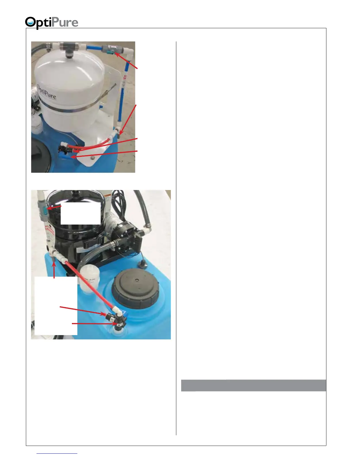
Optional RP Assembly Location
The Repressurization Pump and Buffer Tank assembly
is on a stand that can be remote from the storage tank.
If this type of installation is required, the RP Assembly
should be built as a remote unit from the OptiPure,
with additional installation instructions supplied.
Buffer Tank
Valve
- Shown in the
normal positon
Repressur-
ization Assy
Outlet
Optimized
Water Inlet
Tank Inlet
Divert Valve-
Shown in the
normal positon
50 Gallon Storage Tank
Repressurization
Assy Outlet
Optimized
Water Inlet
Tank Inlet Divert
Valve - Shown in
the normal positon
Buffer Tank Valve
- Shown in the
normal positon
16 Gallon Storage Tank