xiii
List of Figures
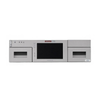
1–1 Drive Expansion Module (rear view)....................................................................................... 1-2
1–2 Library Modules (top view) ...................................................................................................... 1-3
1–3 Electronics Control Module....................................................................................................... 1-4
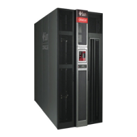
1–4 SL8500 Internal view (with bulk CAP) .................................................................................... 1-5
1–5 SL8500 Internal View (with rotational CAPs)......................................................................... 1-6
1–6 Keypad.......................................................................................................................................... 1-8
2–1 Sample Library Layout (Top View).......................................................................................... 2-2
2–2 Weight Pad Locations................................................................................................................. 2-6
2–3 Conduit and Cable Routing (Rear View) ............................................................................. 2-10
2–4 Fire Suppression Ceiling Access (viewed from the top of the library) ............................ 2-11
2–5 Pass-thru Port Planning Example.......................................................................................... 2-12
7–1 Library Complex Partitioning Example .................................................................................. 7-4
17–1 Emergency Robotic Stop Switch............................................................................................ 17-3
C–1 Internal Library versus HLI-PRC Addressing (top view of library) .................................. C-2
C–2 Tape Drive Internal Library Addressing (viewed from front of library) .......................... C-4
C–3 Bulk CAP Slot Arrays................................................................................................................ C-5
C–4 Pass-thru Port Planning Example............................................................................................ C-8
C–5 Tape Drive HLI-PRC Addressing (viewed from front of library) ...................................... C-9
C–6 Bulk CAP HLI-PRC Addressing ............................................................................................. C-9
C–7 Rotational CAP HLI-PRC Addressing.................................................................................. C-10
C–8 Physical Hardware Numbering of Tape Drive (viewed from rear of library)................ C-10
C–9 Comparison of Tape Drive Numbering (viewed from front of the library).................... C-11
D–1 Redundant Electronics Configuration Examples.................................................................. D-2
E–1 ACSLS Dual TCP/IP with Shared Subnets............................................................................ E-4
E–2 ACSLS Dual TCP/IP ................................................................................................................. E-5
E–3 ACSLS High Availability Dual TCP/IP ................................................................................. E-5
E–4 ELS/HSC Dual TCP/IP ............................................................................................................ E-6
F–1 Multi TCP/IP Connections to a Library Complex................................................................ F-2
F–2 Dual and Multi TCP/IP Connections to a Library Complex .............................................. F-2
H–1
Code 39 Barcode Standard — Letter A................................................................................... H-1
H–2 Code 39 Barcode Standard — Inter-Character Gap.............................................................. H-1
H–3 Barcode Placement Standards (T10000 and LTO)................................................................. H-3
H–4 Cartridge Label Orientation ..................................................................................................... H-6
H–5 White Area on Separate Media ID Label................................................................................ H-6
H–6 Mis-aligned Media ID Label..................................................................................................... H-7