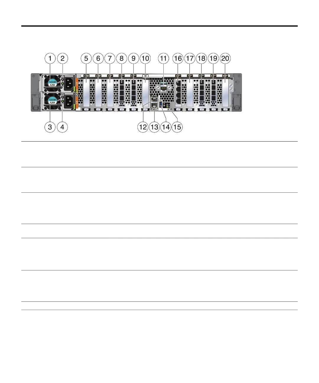
Back Panel Components
1 Power Supply Unit (PSU) 1 2 PSU 1 status indicators (top to bottom):
■ Attention (amber)
■ Power/OK (green)
3 PSU 0
4 PSU 0 status indicators (top to bottom):
■ Attention (amber)
■ Power/OK (green)
5 Second PCIe option (slot 1) 6 Third PCIe option (slot 2)
7 Fifth PCIe option (slot 3) 8 External SAS-3 HBA (slot 4) 9 Slot 5:
■ High-end model: External SAS-3 HBA
■ Mid-range model: Filler panel; slot not
available
10 Not available 11 Serial management (SER MGT) RJ-45
serial port
12 Service Processor (SP) NET MGT port
13 Network (NET) 100/1000BASE-T RJ-45
Gigabit Ethernet (GbE) port: NET 0
14 USB 3.0 port 15 System status LEDs:
■ Locate (white) - left
■ Attention (amber) - right, top
■ Power/OK (green) - right, bottom
16 Ethernet cluster interface card (slot 6) 17 First PCIe option (slot 7) 18 Slot 8:
■ High-end model: External SAS-3 HBA
■ Mid-range model: Filler panel; slot not
available
19 External SAS-3 HBA (slot 9) 20 Fourth PCIe option (slot 10)
Install the Hardware
For detailed information, see the Oracle ZFS Storage Appliance Installation Guide available from https://docs.
oracle.com/en/storage.
3