FRAGILE!
Even so, the freight people will throw
the box
around
as
if it were filled
with
junk.
The
survival of
the
unit depends almost solely on
the
care taken in
packingl
APPENDIX
A:
ALIGNMENT
INSTRUCTIONS
This section of the manual is
included primarily
for
purposes of reference,
as PERIODIC
COMPLETE
ALIGN-
MENT IS NOT RECOMMENDED
OR NECESSARY.
Com-
plete alignment is
a
step-by-step
procedure
which
assumes
that none
of
the trimmer controls
are correctly
adjusted.
IF THE REQUIRED
TEST EQUIPMENT
IS NOT
AVAILABLE,
DO NOT ATTEMPT TO PERFORM
COMPLETE
ALIGN-
MENT,,
Required Instrumentation:
The following instrumentation
is required for
complete
alignment:
(1)
Audio
Sinewave
Generator, with
less than
0.05%
residual harmonic distortion
(2)
Digital Voltmeter, basic
DC
accuracy 0.1% or better
(3)
Audio Voltmeter/Harmonic
Distortion
Meter with 1
megohm or higher input
impedance
(e.g.
H-P 334A)
(4)
Triggered
Sweep Oscilloscope
with
X-Y capability
and minimum 5 MHz vertical
bandwidth
Setup
for
Complete Alignment:
Complete alignment
must be performed
on
a
test
bench
away
from strong RF fields. Before
commencing
align-
ment, apply
power and allow 30 minute
warmup with
cov-
ers in
place.
Remove
the
top and bottom
covers
imme-
diately before starting
alignment procedure.
ALIGN-
MENT
MUST
BE
PERFORMED SEQUENTIALLY.
DO
NOT SKIP STEPS. Alignment points
can be found on
page 1
1
.
Alignment Procedure:
(1)
Connect
digital
voltmeter across
C605,
and read
voltage.
(2)
Adjust
P601
for
a
reading of +15.00 volts
on
DVM.
(3)
Jumper chassis and circuit
grounds together.
(4)
Turn
P210
(broadband
FET
bias)
CW
until the
GAIN
REDUCTION meter indicates that
gain reduction
is
beginning. Back off
P210
until
no further
change is
noted in
GAIN REDUCTION.
(5)
Adjust P212 (G/R Meter Cal)
until
the
GAIN REDUC-
TION meter indicates 100%.
(6)
Connect oscillator to
LEFT AUDIO INPUT. Adjust
oscillator
for
5 kHz. Adjust
INPUT
ATTEN
to
12
o'clock.
Increase oscillator
output until
GAIN
REDUCTION
meter indicates
-8.5
dB
.
(7)
Connect oscilloscope to
SCOPE
OUTPUT
of
distortion
analyzer.
Connect input of
distortion
analyzer
to
the
left channel
broadband limiter output
(terminal
29),
which
is a
fork
terminal
close to
the
right
rear of the
limiter board when
viewed
from
the front.
Operate
distortion analyzer so that the oscilloscope
displays
the input to the distortion
analyzer (normally
the
"SET LEVEL"
mode).
Operate
the
scope in
NORMAL
TRIGGER
mode, and adjust
trigger
level
so scope
barely stops triggering.
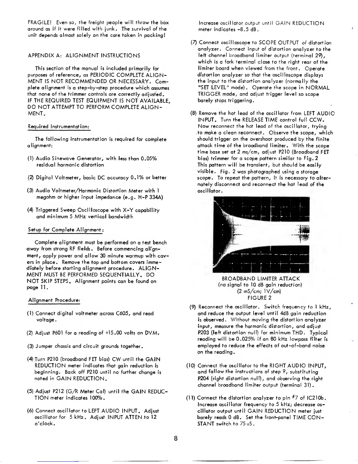
(8)
Remove
the
hot lead of the oscillator from
LEFT
AUDIO
INPUT.
Turn
the
RELEASE
TIME
control
full
CCW.
Now reconnect the hot lead
of
the
oscillator, trying
to make
a
clean reconnect. Observe the
scope, which
should trigger on the overshoot
produced by the
finite
attack time of the broadband
limiter. With the
scope
time base set at 2 ms/cm, adjust
P210
(Broadband
FET
bias)
trimmer
for
a
scope pattern similar to
Fig.
2
This pattern will be transient, but should be
easily
visible.
Fig.
2
was
photographed using
a
storage
scope. To repeat
the
pattern, it is
necessary to alter-
nately disconnect and reconnect the hot lead
of the
oscil lator.
BROADBAND
LIMITER
ATTACK
(no signal
to 10
dB
gain reduction)
(2
mS/cm; IV/cm)
FIGURE
2
(9)
Reconnect
the oscillator. Switch frequency to 1
kHz,
and reduce
the output level until 4dB gain
reduction
is
observed. Without
moving
the distortion
analyzer
input, measure the harmonic distortion,
and adjust
P203
(left distortion null)
for
minimum
THD.
Typical
reading
will
be 0.025% if an 80 kHz lowpass
filter is
employed to reduce the effects
of
out-of-band
noise
on the reading
.
(10)
Connect
the oscillator to the
RIGHT AUDIO
INPUT,
and
follow the
instructions of
step
9,
substituting
P204
(right distortion null), and observing the
right
channel
broadband limiter output
(terminal
31).
(11)
Connect the distortion
analyzer
to pin
^7
of
1C2
1 0b
.
Increase
oscillator frequency to 5 kHz;
decrease os-
cillator output until
GAIN REDUCTION meter just
barely reads 0 dB. Set
the front-panel
TIME CON-
STANT
switch to
75
uS.
8
 Loading...