The output
may be used
to drive
either
balanced or
unbalanced-and-floating
inputs
of external
equipment.
A
three
conductor
shielded
cable
should be used, with
the
inner
conductors
connected to
the 418 output and
signal
ground,
and
the shield
terminated
to the 418 chassis
ground, and
unterminated
at the
other end.
The
comments
concerning
ground loops
in
INSTALLATION: MECHANICAL
(above),
should
be noted.
In most cases,
the
balanced
input will
provide
ground-loop
protection
if
grounding
is effected
as
described
above.
The 418's
VU
meter,
in OUTPUT
positions, is connect-
ed
to the
output
of the 418's line
amplifier before the
OUTPUT
ATTEN
control in
order
to avoid reflecting
meter rectifier
distortion into the
output. Therefore,
this metering
position
will not
show
any adjustments of
the OUTPUT
ATTEN
control
.
First, the attack
time of the
418
is moderate (in the
order
of 2 or
3
milliseconds)
.
Therefore, fast -rising
waveforms will overshoot at
the 418 output.
The
over-
shoots are
sufficiently short
so
that they can be clipped
by the recording
or
transmission medium
following the
418 without audible ill effects, provided that said
media
can
themselves clip. Examples
of
suitable
media are
magnetic tape
(whose saturation characteristic provides
an
ideal "soft" clipping characteristic), and
optical
film, which has
a
much more sudden
clip
point,
but
which can be
clipped without damage to the medium.
On
the other
hand, disc
recording requires absolute
protection in order
to avoid
overcutting and/or cutter
lift. Therefore, in the case
of disc transfer,
the
418
should be followed by some
sort of absolute protection,
such
as a
clipper
or a
very fast
limiter.
Power:
The
power
transformer can
be wired
for
105-125
VAC
or
210-250
VAC
operation,
50 or 60 Hz.
The
nominal
voltage
for
which the unit
is wired is
marked on
the
carton.
If
the unit is
wired
for 230
volts,
a
warning
tag
is also
affixed
to the
line cord.
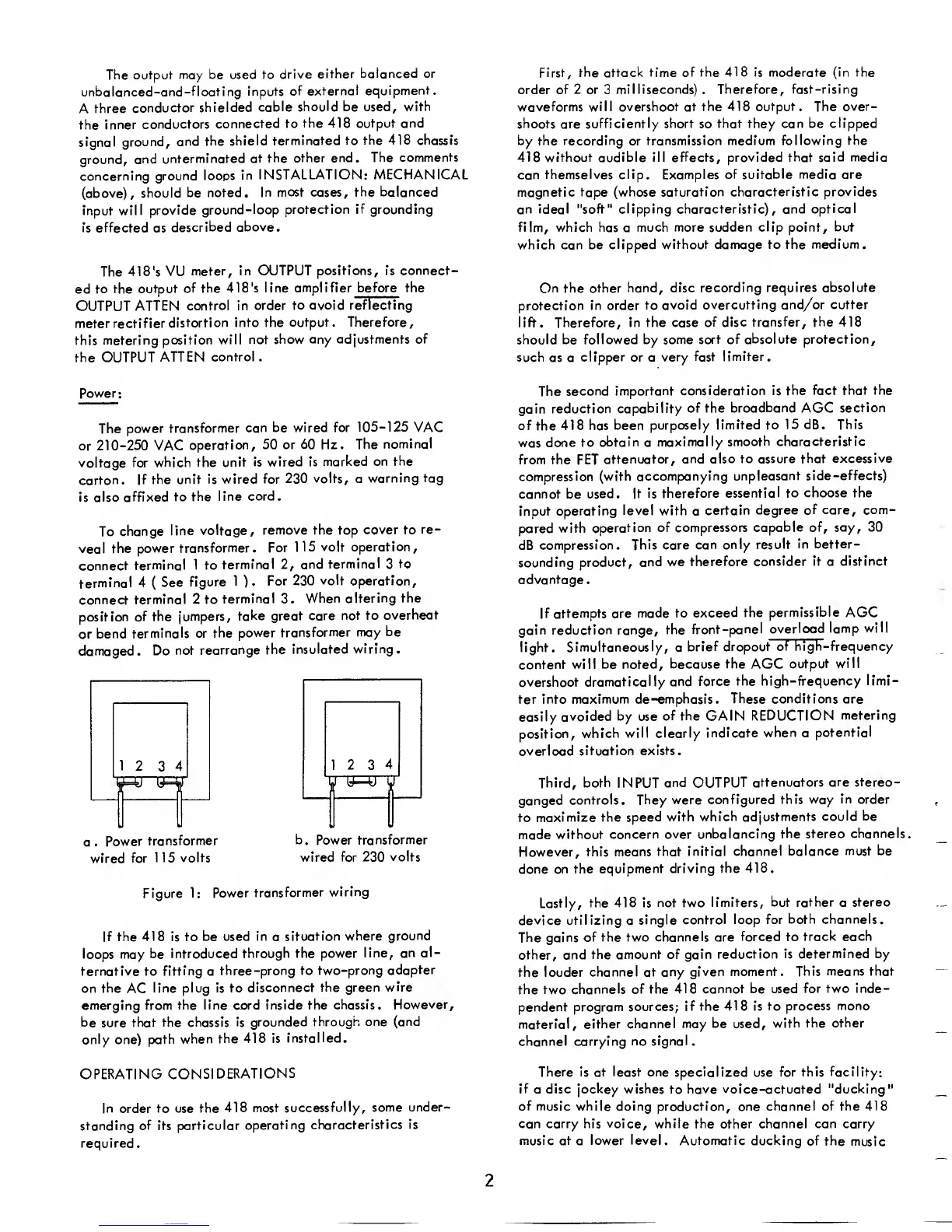
To
change
line voltage,
remove the top
cover to
re-
veal
the power
transformer.
For
115
volt
operation,
connect
terminal
1 to
terminal
2,
and
terminal
3
to
terminal
4
(
See
figure 1
)
.
For
230 volt operation,
connect
terminal 2 to
terminal
3.
When altering
the
position
of
the jumpers,
take
great care not to
overheat
or
bend
terminals
or
the power
transformer
may be
damaged.
Do
not
rearrange
the
insulated wiring.
a .
Power
transformer
wired
for
115
volts
b
.
Power
transformer
wired for 230 volts
Figure
1:
Power
transformer
wiring
If
the
418
is to
be used in
a
situation
where ground
loops may
be introduced
through the
power line, an
al-
ternative
to fitting
a
three-prong to
two-prong
adapter
on
the
AC
line plug is to
disconnect
the green
wire
emerging from the line cord inside
the chassis.
However,
be sure that
the chassis is
grounded
through one (and
only
one)
path
when
the
418
is
installed.
The
second
important
consideration is
the fact that the
gain
reduction capability
of the
broadband
AGC
section
of the
418
has
been
purposely limited to
1 5 d
B
.
This
was
done to
obtain
a
maximally smooth
characteristic
from the
FET
attenuator,
and also to assure
that excessive
compression
(with accompanying
unpleasant
side-effects)
cannot be used. It
is therefore
essential to
choose the
input
operating
level with
a
certain degree
of care, com-
pared
with
operation
of compressors capable
of,
say,
30
dB
compression.
This care
can only result
in better-
sounding
product, and we
therefore
consider it a
distinct
advantage.
If attempts
are
made to exceed the
permissible
AGC
gain
reduction range,
the front
-panel
overload
lamp
will
light.
Simultaneously, a
brief
dropout
of
high-frequency
content
will be noted,
because
the
AGC
output
will
overshoot
dramatically
and force the
high-frequency limi-
ter into
maximum de-emphasis. These conditions are
easily
avoided
by
use
of the
GAIN
REDUCTION
metering
position,
which
will clearly
indicate
when
a
potential
overload
situation exists.
Third,
both
INPUT
and
OUTPUT
attenuators
are stereo-
ganged
controls. They
were configured this way
in order
to
maximize
the speed with
which adjustments
could be
made
without
concern over unbalancing
the stereo
channels.
However,
this
means that initial
channel balance must
be
done on the
equipment
driving the
418.
Lastly,
the 418 is
not two limiters,
but rather
a
stereo
device
utilizing
a
single
control loop
for both channels.
The
gains
of the two
channels
are
forced
to track each
other, and
the amount
of
gain
reduction
is determined
by
the louder
channel at any
given
moment. This means that
the two
channels of the
418 cannot be used
for two
inde-
pendent
program sources;
if the
418
is
to process
mono
material,
either channel may
be
used,
with the
other
channel
carrying no signal.
OPERATING
CONSIDERATIONS
In
order to use
the 418 most
successfully,
some
under-
standing
of its particular
operating
characteristics
is
required.
There is at least one specialized
use
for this facility:
if
a disc
jockey wishes
to have voice-actuated
"ducking
1
of music while doing
production, one
channel of the 418
can carry his voice, while the other channel can carry
music at
a
lower
level.
Automatic
ducking of
the
music
2
 Loading...