should be
tightly wrapped
around the
674A
Equalizer and taped in place to
prevent
the unit from
shifting out of
its packing
and contacting the walls of
the carton.
The carton
should be packed
evenly
and fully with the
packing material
filling all
voids such that
the unit cannot
shift in the
carton. Test for
this
by
closing but not
sealing the
carton and shaking
vigorously.
If the unit can be felt or
heard to
move,
use
more packing.
The carton should be
well-sealed with
3"
reinforced sealing tape applied across
the
top and
bottom of
the carton in an
"H" pattern.
Narrower
or
parcel-post type
tapes will not stand the
stresses applied to
commercial shipments.
The package
should
be
marked
with the name of the shipper,
and the words
in
red:
DELICATE
INSTRUMENT,
FRAGILE!
Even so,
the
freight people
will throw
the box around as if
it were
filled with junk.
The survival
of
the unit depends
almost solely
on the care
taken in packing!
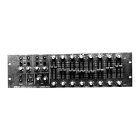
4:
CIRCUIT
General: Except for
the power supply, the left and right
channels of the
674A
are
DESCRIPTION
independent
and identical.
In the following
discussion, the
LEFT CHANNEL
will be
described.
The circuitry is divisible
into six major blocks.
These are:
1)
input buffer
2)
equalizer
3)
highpass filter and
output buffer
4)
lowpass filter and output
buffer
5)
overload
indicator
6)
power
supply
These will
be
described in order.
Input Buffer: The signal
enters the
674A
in
balanced form.
Cl,
C3 shunt
RF
from
the input leads to
the chassis. These capacitors are not effective at
VHF
and
higher frequencies; therefore, ferrrte
beads have
been
placed
around the input
and
output leads
to
suppress such high
frequency
RF. It should
be noted that this
degree
of RF-proofing is moderate but adequate
for a vast majority of installations.
However, installation next to a
high-power
transmitter may still cause
problems.
Additional
RF
suppression,
careful examination of
the
grounding scheme, and
other
considerations
familiar to
the broadcast
engineer may
have to be used
in
conjunction with
the 674A's built-in
RF
suppression.
The filtered
signal is applied
to
ICIOI,
a
very low-noise
opamp
configured as
a
differential amplifier
with a gain
of 0.5. When
both
non-inverting and
inverting
inputs are
driven by
a
source
impedance
which is small
with respect to I00K
(such
as
600 ohms or less),
the amplifier is
essentially insensitive
to signal
components
that appear equally
on the non-inverting and
inverting inpuls (such as
hum), and
responds
with full gain to the
difference between
the non-inverting and
inverting
inputs. Thus
it serves as an
"active transformer".
Ordinarily,
best results are
obtained
for unbalanced
signals if the
non-inverting input
is grounded and
the
inverting input is driven.
The
GAIN
control is
located after
ICIOI. Therefore,
ICIOI
will
overload
if its
differential
input exceeds
approximately
+26dBm.
The
OVERLOAD
lamp
will
indicate this.
26
 Loading...