Appendix:
Interconnections
and Grounding
Small systems usually come
together
easily because cable runs
are usually
short
and the
interconnections between
various pieces of
equipment are not
terribly
complex.
Therefore, do not be
intimidated by
the seeming
complexity of
the
discussion on
interconnections and
grounding below.
This
is more
information than
most people
will ever need to
successfully install a
small system; we
have included
it in case things don't work right
and you need to find out
why.
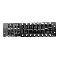
DRIVING THE
674A
Both
"+"
and sides of
the
674A
inputs
are bypassed to
chassis ground
for
RF
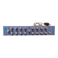
FROM
HIGH-
lOOOpF capacitors.
To assure common
mode rejection,
and to assure
that
these capacitors do not affect
the frequency
response of
the system,
the output
IMPEDANCE/HIGH- impedance
of the equipment
driving the
674A
should be
600 ohms or less.
Most
SOURCES
P
r
°fess
'
ona
'
an<
^
semi-professional sound
equipment will satisfy
this
requirement.
The
674A
can
be driven by
unbalanced sources up
to
10,000
ohms
(such as
the
outputs of some
vacuum tube preamps) by
removing the
lOOOpF capacitors from
the
"+"
inputs, and
driving these inputs from
the hot side of the driving
equipment's
outputs.
(See the section below on Grounding
for an explanation of
balanced and
unbalanced
connections.)
If the lOOOpF capacitors are
left in place and the source
impedance is
I0K,
the
capacitors will cause a high frequency
rolloff
which is 3dB down at
16kHz,
and
which rolls off
at
6dB/octave
thereafter.
The absolute clipping level
of
the
674A input
is
+26dBm. If
such clipping
occurs,
it will
cause
the
OVERLOAD lamp to
flash on and off regardless of
the setting of
the
GAIN
control.
If
levels
greater
than +26dBm are
expected,
an
external loss pad must be used
before
the
674A
input.
The Audio Cyclopedia
,
Section
5,
contains instructions for
making
such pads.
(Tremaine,
H.M.: The Audio Cyclopedia
,
Second Edition,
Indianapolis, Howard W. Sams & Co.,
Inc.,
1969).
GROUNDING
Grounding serves two purposes: it joins the ground references of various pieces
of
electronic equipment, and it shields the electronics from various electric fields
(RFI
and hum).
(Interference
caused by magnetic fields is
not decreased by conventional shielding,
and special magnetic shielding materials
must
be
used where
hum is a problem. In
audio, such shielding
is
ordinarily
used with low-level
magnetic transducers like tape
heads, magnetic phono
cartridges, and dynamic microphones,
and
with
low-level
transformers. Line-level
equalizers such
as
the
674A
are not normally sensitive to
this sort of interference.)
There
are
two types
of
ground: circuit and chassis. Circuit ground serves
as a
ground reference for the electronics. Chassis ground permits
use of
the chassis
as a
shield
in the same way that the shield
on
shielded cable protects the inner
conductors. Whether the
circuit and chassis grounds are identical, are separate, or
are intentionally
joined depends on
the type of equipment
and the interconnecting
scheme.
31
 Loading...