11
ENGLISH
10
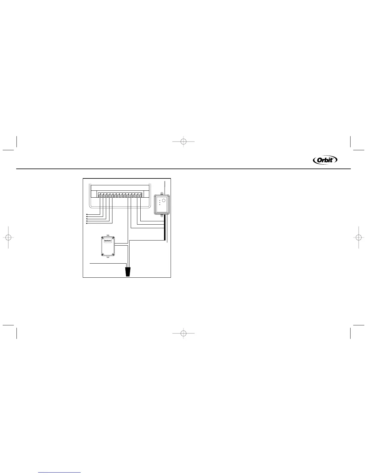
using a wire nut. (See
figure 7).
4. Connect the white
(common) wire from the
rain/freeze receiver to
the common terminal on
the timer.
5. Connect the (2) red
“24V” wires to the 24V
terminals of the timer.
SECTION 3
Operation
Checks
Verify Correct Wiring
Select a sprinkler station/
zone that is visible and in
reach of the Rain/Freeze
receiver and sprinkler timer. After Manually activating the station/zone, on
the sprinkler timer, press the”Manual Override” button on the receiver. The
top light should indicate that the system is being overridden. If the light
does not illuminate, check the red wire connections. If the light is illuminat-
ed then the zone watering (and the pump, if installed) should shut off. If the
zone continues to water check the white and yellow (or green) wire con-
nections.
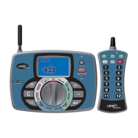
Verify Communication between the Transmitter and Receiver
Verify that the Control Switch, located on the bottom of the transmitter, is
set on either the “Rain” or “Rain/Freeze” position. Next, press the manual
test stem on the transmitter until you hear a light click. While holding the
test stem down verify that the receiver “Sensor Active” light is illuminated.
If the light is illuminated, the communication is set. If the light does not illu-
minate, press and hold the “Transmitter Program” button for at least two
seconds. Once all three lights are illuminated, press the manual test stem
repeatedly until the three lights start flashing. When the lights stop flashing
press the manual test stem again, the “Sensor Active” light should illuminate.
If problems persist check your wiring or call our technical support group.
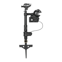
Mounting the Transmitter
Mount the rain/freeze sensor to a gutter with the provided thumb screw, or
to a flat surface, with provided screws, where it will be exposed to direct,
unobstructed rainfall (but away from sprinkler spray). The test stem must
be upright. For solar powered models the transmitter must be mounted so
that the solar cell can receive direct, unobstructed sunlight. (See figure 8)
Figure 7: Wiring Sprinkler timer with booster pump but
with out Sensor terminals