3
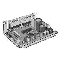
No. Name Description
1 Power supply connector (CN1) Connects the power supply.
2 I/O signals connector (CN2) Connects the I/O signals.
3 Motor connector (CN3) Connects the motor.
4
Motor operating current
setting switch (RUN)
Sets the operating current of the motor.
5
Motor standstill current
potentiometer (STOP)
Sets the current when the motor is at a
standstill.
6
Pulse input mode setting
switch (SW-1)
Switches the pulse input mode between
1-pulse input mode and 2-pulse input
mode.
The factory setting of the pulse-input
mode depends on the destination
country.
Step angle setting switches
(SW-2, SW-3, SW-4)
Set a step angle by selecting it from
among the 5 step angles.
7 POWER LED (Green)
This LED remains lit while the power
supply is input.
Installation
Location for installation
The driver is designed and manufactured to be incorporated in equipment.
Install it in a well-ventilated location that provides easy access for inspection.
The location must also satisfy the following conditions:
y
Inside an enclosure that is installed indoors (provide vent holes)
y
Operating ambient temperature 0 to +40 °C (+32 to +104 °F) (non-freezing)
y
Operating ambient humidity 85% or less (non-condensing)
y
Area that is free of explosive atmosphere or toxic gas (such as sulfuric gas)
or liquid
y
Area not exposed to direct sun
y
Area free of excessive amount of dust, iron particles or the like
y
Area not subject to splashing water (rain, water droplets), oil (oil droplets)
or other liquids
y
Area free of excessive salt
y
Area not subject to continuous vibration or excessive shocks
y
Area free of excessive electromagnetic noise (from welders, power
machinery, etc.)
y
Area free of radioactive materials, magnetic elds or vacuum
y
1,000 m (3,300 ft.) or lower above sea level
Installation direction
Install the driver on a metal plate having excellent vibration resistance in
vertically or horizontally. If the driver is installed under conditions other than
vertical or horizontal position, its heat radiation eect will deteriorate.
The items shown below are necessary in order to install the driver. The items
are not included and must be provided by the customer.
Torque the mounting screw to 0.5 N·m (71 oz-in).
y
M3 screw ........................ 2 pcs.
y
M3 spring washer .......2 pcs.
y
M3 at washer..............2 pcs.
y
M3 nut.............................2 pcs.
(Not necessary if screw holes are provided in the enclosure.)
There must be a clearance of at least 25 mm (0.98 in.) in the horizontal and
50 mm (1.97 in.) in the vertical directions, between the driver and enclosure
or other equipment within the enclosure. When two or more drivers are to be
installed side by side, provide 20 mm (0.79 in.) and 50 mm (1.97 in.) clearances
in the horizontal and vertical directions, respectively.
y
Install the driver inside an enclosure.
y
Do not install any equipment that generates a large amount of heat
or noise near the driver.
y
If the ambient temperature of the driver exceeds 40 °C (104 °F),
improve the ventilation condition. If the surface temperature of the
driver’s MOSFET array exceeds 85 °C (185 °F), review the operating
conditions.
y
The case containing the MOSFET arrays is insulated.
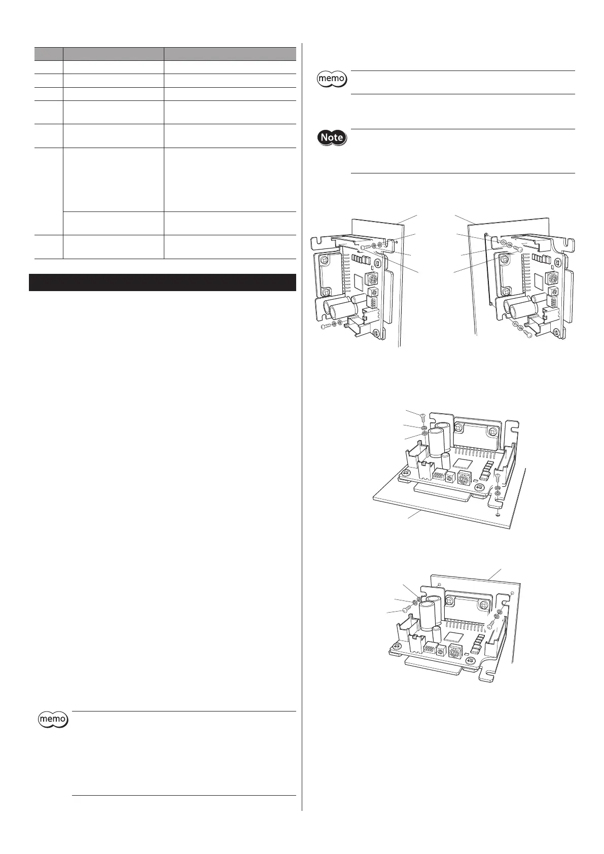
Installation method
Install the driver using either of the "cutout for mounting A" or "cutout
for mounting B." Do not concurrently use both cutouts.
z
Vertical installation
When installing the driver vertically, orient the driver so that the
power element faces up and the aluminum electrolytic capacitor faces
down. If the driver is installed upside down, heat generated by the
power element may damage the aluminum electrolytic capacitor.
M3 screws
Spring washers
Flat washers
Metal plate
or mounting A
for mounting B
z
Horizontal installation
When using the cutout for mounting A
Flat washers
Metal plate
When using the cutout for mounting B
M3 screws
Flat washers
 Loading...