EasyManua.ls Logo

Oriental motor VEXTA TD Series - User Manual

Oriental motor VEXTA TD Series
12 pages
Print Icon
To Next Page IconTo Next Page
Loading...
Unauthorized reproduction or copying of all or part of this operating manual is prohibited.
If you have damaged or misplaced the operating manual and require a new copy, contact your nearest
Oriental Motor office.
The operating manual is subject to change without prior notice for the purpose of improvement or change
in product specifications, or to improve the manual itself.
The utmost care has been taken to ensure that all information contained in the operating manual is cor-
rect. However, please contact your nearest Oriental Motor office should you find any unclear descrip-
tions, errors or omissions.
is a trademark of Oriental Motor Co., Ltd., registered in Japan and other countries.
Windows is a registered trademark of Microsoft Corp.
Other products and companies referred to in this manual are the trademarks or registered trademarks
of the respective companies. All references to other manufacturer’s products made in this manual are
intended strictly for reference purposes and do not constitute a requirement or recommendation re-
garding the use thereof. Oriental Motor Co., Ltd. shall in no way be liable for the performance or com-
patibility of other manufacturers’ products.
© Copyright ORIENTAL MOTOR CO., LTD. 2001
HP-0021
5-Phase Stepping Driver with Built-in Oscillator
TDSeries
Type V
(potentiometer type)
OPERATING MANUAL
Thank you for purchasing an Oriental Motor product.
This operating manual describes product handling
procedures and safety precautions.
Please read it thoroughly to ensure safe operation.
Always keep the manual where it is readily available.
POWER
SPEED
A
C
C
E
L
D
E
C
E
L
J
-
L
I
M
R
U
N
S
T
O
P
O
/P
1SHOT
O
F
F
C
D
1
2
3
O
N
1
1
Introduction …………………………… 2
Safety precautions……………………3
Precautions for use ………………… 5
Preparation …………………………… 6
Checking the product ………………6
Applicable motors …………………6
Names and functions of parts …… 7
Installation …………………………… 8
Location for installation …………… 8
Installation method ………………… 8
Connection …………………………… 9
Power connection …………………9
Motor connection…………………… 9
I/O Connection ……………………10
Connection of I/O …………………11
Explanation of I/O …………………12
Timing chart ………………………14
Setting …………………………………15
Setting of operating speeds and
acceleration/deceleration rates 15
Switch settings ……………………16
Setting of motor currents …………17
Overvoltage protection function ……19
Inspection ……………………………20
Troubleshooting and
corrective actions ……………………20
Specifications ………………………22
Dimensional drawing ………………23
Table of Contents
Please contact your nearest ORIENTAL MOTOR office for further information.
ORIENTAL MOTOR U.S.A. CORP.
Technical Support Line Tel:(800)468-3982
Available from 8:30 AM to 5:00 PM, P.S.T.
ORIENTAL MOTOR (EUROPA) GmbH
Headquarters and Düsseldorf Office
Tel:0211-5206700 Fax:0211-52067099
Munich Office
Tel:08131-59880 Fax:08131-598888
Hamburg Office
Tel:040-76910443 Fax:040-76910445
ORIENTAL MOTOR (UK) LTD.
Tel:01252-519809 Fax:01252-547086
ORIENTAL MOTOR (FRANCE) SARL
Tel:01 47 86 97 50 Fax:01 47 82 45 16
ORIENTAL MOTOR ITALIA s.r.l.
Tel:02-3390541 Fax:02-33910033
TAIWAN ORIENTAL MOTOR CO., LTD.
Tel:(02)8228-0707 Fax:(02)8228-0708
SINGAPORE ORIENTAL MOTOR PTE LTD.
Tel:(745)7344 Fax:(745)9405
ORIENTAL MOTOR (MALAYSIA) SDN BHD
Tel:(03)79545778 Fax:(03)79541528
INA OM LTD. (KOREA)
Tel:(032)822-2042~3 Fax:(032)819-8745
ORIENTAL MOTOR CO., LTD.
Headquarters Tokyo, Japan
Tel:(03)3835-0684 Fax:(03)3835-1890
Printed on Recycled Paper
Question and Answer IconNeed help?

Do you have a question about the Oriental motor VEXTA TD Series and is the answer not in the manual?

Summary

Introduction

Product Overview and Features

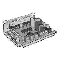
Key features and a brief description of the driver.

System Configuration

Specifications

Safety Precautions

General Safety Warnings

Warnings about hazards and proper handling procedures.

Installation & Connection Safety

Safety rules for installing and connecting the driver.

Operation and Handling

Disassembly and Modification

Disposal

Troubleshooting and Corrective Actions

Inspection

Inspection Notes and Items

Notes on static electricity and key inspection points.

Precautions for Use

Heat Sink and I;O Wiring

Guidelines for managing heat and wiring I/O cables correctly.

Preparation

Product Checking and Applicable Motors

Instructions for verifying the product and motor compatibility.

Overvoltage Protection Function

Names and Functions of Parts

Control Potentiometers

Description of potentiometers for speed, current, and rate adjustments.

Control Switches

Explanation of switches for mode selection and signal types.

Indicators and Terminals

Information on LED indicators and connection terminals.

Installation

Location, Method, and Orientation

Guidelines for optimal driver placement and mounting.

Setting of Motor Currents

Operating and Standstill Current Settings

Step-by-step guide for current adjustments.

Connection

Setting Rates and Time

How to adjust acceleration, deceleration, and jerk-limit settings.

Switch Settings

Configuration options using driver switches.

Power and Motor Connection

Instructions for connecting power supply and motor leads.

I;O Connection

Connection Examples

Illustrative diagrams for different I/O setups.

Setting Operating Speeds

Speed Setting Methods

Overview of internal potentiometer, external potentiometer, and DC voltage speed control.

Timing Chart

Oscillator Mode Timing

Timing diagrams specific to oscillator mode operation.

I;O Connection Details

Cable Connection and Function Tables

Guides for connecting I/O cables and tables of I/O functions.

Explanation of I;O

Input and Output Signals

Descriptions of how input signals work and what output signals indicate.

Overview

VEXTA TD Series Type V 5-Phase Stepping Driver with Built-in Oscillator

This document describes the VEXTA TD Series Type V 5-Phase Stepping Driver, a compact, lightweight bipolar constant-current driver with a built-in oscillator, designed for driving 5-phase stepping motors using the New Pentagon drive system. It is suitable for general industrial equipment and offers precise speed control and various operational features.

Function Description

The TD Series Type V driver features a built-in oscillator for easy and accurate speed control. It supports two speed-setting methods: one using the built-in potentiometer and another using an external potentiometer or external DC voltage. This allows for dual-speed operation by switching between the two potentiometers or between the internal potentiometer and an external DC voltage source.

A key feature is the "Jerk-limit control function," which employs special acceleration/deceleration profiles to achieve smooth speed transitions, thereby suppressing vibration when the motor moves from acceleration to constant-speed operation. This function helps to reduce mechanical stress and improve the overall smoothness of motion.

The driver also facilitates easy synchronization of two units. By connecting the oscillator output of one driver to the pulse input of another, synchronized operation can be achieved, which is useful in applications requiring coordinated motion.

The device includes an "Auto Current Cutback function" that automatically reduces the motor current to a standstill current approximately 100 ms after the motor stops. This feature helps to reduce heat generation and power consumption when the motor is idle. This function can be enabled or disabled via a switch.

The driver supports both "Oscillator mode" and "Pulse-train mode," selectable via a mode switch. In Oscillator mode, the driver operates via its built-in oscillator. In Pulse-train mode, it operates based on external pulse-train inputs. The START/STOP signal type can also be configured as either "level input" or "one-shot input" depending on the application's control requirements.

An "Overvoltage protection function" is integrated into the driver. If the inverter voltage exceeds a specified value, this function activates, immediately stopping the motor and causing the POWER LED to blink. This protects the driver and motor from potential damage due to overvoltage conditions. After activation, the cause of the overvoltage must be removed, and the power cycled to reset the protection function.

Important Technical Specifications

Model Variants:

  • TD514-V: Rated output current of 1.4 A.
  • TD528-V: Rated output current of 2.8 A.

Power Input:

  • Voltage: 12 to 24 VDC ±10%.
  • Current:
    • TD514-V: 2.5 A or less.
    • TD528-V: 4.5 A or less.
  • It is crucial to use a DC power source with reinforced insulation on the primary and secondary sides to prevent electric shock.

Excitation Mode:

  • Full-step, 0.72°/step (4-phase excitation).

Operating Modes:

  • Oscillator mode.
  • Pulse-train mode.

Speed Range:

  • 0 to 1500 r/min.

Speed Setting Methods:

  • Built-in potentiometer.
  • External potentiometer (0 to 5 VDC).
  • External DC voltage (0 to 5 V).

Acceleration/Deceleration Rate Setting:

  • Method: Built-in potentiometer.
  • Range: 0 to 3000 ms (at a speed of 1000 r/min).
  • Control: Linear acceleration/deceleration or jerk-limit control.

Jerk-limit Filter Time Setting:

  • Method: Built-in potentiometer.
  • Range: 0 to 250 ms.

Input Signals (Photocoupler input):

  • Input Resistance: 220 Ω.
  • Input Current: 20 mA or less.
  • Signal Voltage: H: 4.5 to 5 V, L: 0 to 0.5 V.
  • Inputs: START/STOP (pulse input in pulse-input mode), RUN/BRAKE, CW/CCW, HOLD OFF, Speed setting method selection (EXTVR).

Output Signals (Photocoupler/open-collector output):

  • External Use Conditions: 26.4 VDC, 20 mA or less.
  • Outputs: Pulse output (POUT+ / POUT-).
  • VR-H Output: 5 V output (not isolated from main power input).

External Speed Setting Input:

  • Input Resistance: 47 kΩ.
  • External Potentiometer: 20 kΩ, 1/4 W.
  • External Voltage: 0 to 5 VDC.

Mass:

  • 0.12 kg (3.5 oz).

Ambient Temperature:

  • 0 to 50°C (32 to 122°F).

Applicable Motors:

  • Designed for 5-phase stepping motors with 5 leads connected in a New Pentagon method.
  • Specific models include PK543N-WA, PK544N-WA, PK545N-WA, PK564N-WA, PK566N-WA, PK569N-WA, PK596-NA, PK599-NA, PK5913-NA.
  • The driver's operating current is factory-set to 1.4 A/phase for TD514-V and 2.8 A/phase for TD528-V. For motors with different operating currents (e.g., 0.75 A/phase), the motor operating current adjustment potentiometer must be used to set the appropriate value.

Usage Features

Installation:

  • The driver is designed as an internal component for industrial equipment. It must be installed indoors within a well-ventilated enclosure.
  • Environmental Conditions:
    • Ambient temperature: 0°C to 50°C (non-freezing).
    • Ambient humidity: 85% or less (no dew condensation).
    • Free from explosive/toxic gases, direct sunlight, significant dust/iron powder, water/oil droplets, high salt content, continuous vibration/excessive shock, significant electromagnetic noise, vacuum, radioactive substances, or magnetic fields.
  • Mounting: Secure the driver vertically or horizontally on a flat metal plate with excellent vibration resistance and thermal conductivity using two M3 screws. Avoid leaving gaps along the metal plate.
  • Clearance: Maintain a minimum clearance of 25 mm (0.98 inch) horizontally or 50 mm (1.96 inch) vertically between the driver and enclosure/other equipment. For multiple drivers side-by-side, maintain 20 mm (0.79 inch) horizontally or 50 mm (1.96 inch) vertically between them.

Wiring:

  • Connect power, motor, and I/O signals to the corresponding terminals as shown in the wiring diagrams.
  • Use shielded wire for I/O cables.
  • Keep I/O cables as short as possible and maintain a minimum distance of 300 mm (11.8 inches) from inductive loads (e.g., electromagnetic relays) and power lines (e.g., power-supply cables, motor cables). Do not route I/O cables with power lines in the same duct or conduit.

Setting Motor Currents:

  • Operating Current: Factory-set to 1.4 A/phase (TD514-V) or 2.8 A/phase (TD528-V). To adjust, turn switch 1-3 (CDOFF) to ON, connect a DC ammeter, and use the "Motor operating current adjustment potentiometer (RUN)" to set the desired current. The ammeter reads two-phase current, so current per phase is half the reading. After setting, turn switch 1-3 (CDOFF) to OFF.
  • Standstill Current: Factory-set to approximately 50% of the operating current. To adjust, ensure switch 1-3 (CDOFF) is OFF, connect a DC ammeter, and use the "Motor standstill current adjustment potentiometer (STOP)" to set the desired current, up to a maximum of 50% of the motor's rated current.
  • Important: Set the motor operating current within the motor's rated current. Reduce current for small loads to minimize temperature rise or vibration. Set the standstill current within 50% of the motor's rated current; setting it too high increases heat generation, while setting it too low may affect the motor's ability to start or hold position.

Setting Operating Speeds:

  • Internal Potentiometer: Used for infrequent speed changes or dual-speed operation with an external potentiometer. Speed range: 0 to 1500 r/min.
  • External Potentiometer: Used for remote speed setting or dual-speed operation with the internal potentiometer. Speed range: 0 to 1500 r/min. Use optional part PAVR-20KZ. Turning the potentiometer clockwise increases speed.
  • External DC Voltage: Used for speed setting via a programmable controller or dual-speed operation with the internal potentiometer. Speed range: 0 to 1500 r/min. Use a DC power source (0 to 5 VDC, 1 mA or more) with reinforced insulation.
  • To activate external speed setting, the EXTVR input must be turned ON.

Switch Settings:

  • Mode Switch (O/P, SW 1-1):
    • OFF: Oscillator mode (driver operates via built-in oscillator).
    • ON: Pulse-train mode (driver operates via external pulse-trains).
  • One-shot Switch (1SHOT, SW 1-2):
    • OFF: START/STOP input is "level input."
    • ON: START/STOP input is "one-shot input."
  • Auto Current Cutback Switch (CD OFF, SW 1-3):
    • OFF: Auto Current Cutback function enabled (motor current drops to standstill current 100 ms after stop).
    • ON: Auto Current Cutback function disabled (used for current setting).

Maintenance Features

Inspection Items:

  • Regularly check the driver's mounting screws and power-terminal screws for tightness.
  • Inspect power elements and smoothing capacitors for any bad smell or other abnormalities.
  • The driver uses semiconductor elements, so handle with caution to avoid damage from static electricity.

Troubleshooting and Corrective Actions:

  • Motor doesn't turn:
    • Ensure START or RUN input is ON in oscillator mode.
    • Check if speed is set to 0 (adjust internal/external potentiometer).
    • Verify correct operating mode (SW 1-1 O/P setting).
    • Ensure I/O power source is connected.
  • Motor turns opposite direction:
    • Check DIR input setting.
  • Motor operation unstable:
    • Verify motor cable connection.
    • Check current setting; a value too small reduces motor torque.
  • Motor misses steps during acceleration/operation:
    • Check coupling of motor's output shaft and load shaft.
    • Review load conditions if load fluctuates significantly. Reduce operating speed or increase torque if needed.
    • Reduce acceleration/deceleration rate if too high.
  • Excessive vibration:
    • Adjust jerk-limit filter time to minimize vibration during acceleration transitions.
    • Check current setting; vibration increases if output torque is too large for the load.
  • Overvoltage protection activated:
    • Review load conditions or increase acceleration/deceleration rate.
  • Motor has no holding torque / Motor can be moved by hand:
    • Check motor cable connection.
    • Check current setting; a value too small reduces motor torque.
    • Ensure HOFF input is OFF (excitation ON).

Safety Precautions:

  • General:
    • Do not use in explosive, flammable, corrosive gas atmospheres, or near water/flammable objects.
    • Installation, connection, operation, inspection, and troubleshooting must be performed by qualified personnel.
    • Provide measures to retain the movable part in vertical applications, as the motor loses holding capability when power is cut.
    • If protection function activates, remove the cause and cycle power. Continuing operation without addressing the cause can lead to malfunction.
  • Installation:
    • Install the driver in an enclosure to prevent injury.
  • Connection:
    • Always use the rated voltage power source.
    • Use a DC power source with reinforced insulation on primary and secondary sides.
    • Connect correctly and securely according to wiring diagrams.
  • Operation:
    • Turn off power during power failure to prevent sudden motor starts.
    • Do not turn HOFF input ON while motor is operating, as it will lose holding capability.
    • If POWER LED is unlit, fuse may be blown; turn off power and contact support.
    • Do not repair, disassemble, or modify the driver.
    • Do not use motor/driver beyond specifications.
    • Avoid touching motor/driver heat sink during or immediately after operation due to high temperatures.
    • Do not place flammable objects near motor/driver.
    • Ensure proper ventilation; do not obstruct airflow.
    • Provide a cover for rotating motor parts.
    • Use specified motor/driver combination.
    • Confirm emergency-stop function works.
    • Turn on power only after all control inputs are OFF to prevent accidental starts.
    • Do not touch rotating motor parts during operation.
    • If manual movement of motor shaft is needed, ensure HOFF input is ON.
    • Immediately turn off power if any abnormality is found.
  • Heat Sink Temperature:
    • The driver does not have overheating protection. Ensure the heat sink temperature remains at 80°C (176°F) or below during use to prevent damage.

Disposal:

  • Dispose of the motor and driver as ordinary industrial waste.

Oriental motor VEXTA TD Series Specifications

General IconGeneral
BrandOriental motor
ModelVEXTA TD Series
CategoryDC Drives
LanguageEnglish

Related product manuals