EasyManua.ls Logo

Oriental motor CMD - User Manual

Oriental motor CMD
12 pages
Print Icon
To Next Page IconTo Next Page
Loading...
1
Introduction
Before use
Only qualied personnel of electrical and mechanical engineering should
work with the product.
Use the product correctly after thoroughly reading the "Safety precautions."
In addition, be sure to observe the contents described in warning, caution,
and note in this manual.
The product described in this manual has been designed and manufactured
to be incorporated in general industrial equipment. Do not use for any other
purpose. Oriental Motor Co., Ltd. is not responsible for any damage caused
through failure to observe this warning.
Overview of the product
The products described in this manual are open frame type microstepping
drivers to drive unipolar-connection stepping motors.
Safety precautions
The precautions described below are intended to prevent danger or injury
to the user and other personnel through safe, correct use of the product.
Use the product only after carefully reading and fully understanding these
instructions.
Description of signs
Handling the product without observing the instructions
that accompany a "WARNING" symbol may result in
serious injury or death.
Handling the product without observing the instructions
that accompany a “CAUTION” symbol may result in injury
or property damage.
The items under this heading contain important handling
instructions that the user should observe to ensure the
safe use of the product.
Description of graphic symbols
Indicates "prohibited" actions that must not be performed.
Indicates "compulsory" actions that must be performed.
y
Do not use the product in explosive or corrosive environments, in the
presence of ammable gases, locations subjected to splashing water,
or near combustibles.
Doing so may result in re or injury.
y
Do not forcibly bend, pull or pinch the cable.
Doing so may result in re.
y
Do not turn the AWO input to ON while the motor is operating.
Doing so may result in injury or damage to equipment.
y
Do not disassemble or modify the product.
Doing so may result in injury.
HM-7450-3
OPERATING MANUAL
Thank you for purchasing an Oriental Motor product.
This Operating Manual describes product handling procedures and safety
precautions.
y
Please read it thoroughly to ensure safe operation.
y
Always keep the manual where it is readily available.
For 2-phase Stepping Motor
CMD
Driver
KCC-REM-OMC-001
y
Assign qualied personnel to the task of installing, wiring, operating/
controlling, inspecting and troubleshooting the product.
Failure to do so my result in re or injury.
y
If this product is used in a vertical application, be sure to provide a
measure for the position retention of moving parts.
Failure to do so may result in injury or damage to equipment.
y
Install the product inside an enclosure.
Failure to do so may result in injury.
y
Always keep the power supply voltage of the driver within the
specied range.
Failure to do so may result in re.
y
For the driver power supply use a DC power supply with reinforced
insulation on its primary and secondary sides.
Failure to do so may result in electric shock.
y
Connect the cables securely according to the wiring diagram.
Failure to do so may result in re.
y
Turn o the driver power supply in the event of a power failure.
Failure to do so may result in injury or damage to equipment.
y
Do not use the product beyond its specications.
Doing so may result in injury or damage to equipment.
y
Keep your ngers and objects out of the openings in the product.
Failure to do so may result in re or injury.
y
Do not touch the product during operation or immediately after
stopping.
Doing so may result in a skin burn(s).
y
Do not forcibly bend or pull the cable that was connected to the
driver.
Doing so may result in damage to product.
y
Keep the area around the product free of combustible materials.
Failure to do so may result in re or a skin burn(s).
y
Leave nothing around the product that would obstruct ventilation.
Failure to do so may result in damage to equipment.
y
Do not touch the rotating part (output shaft) while operating the
motor.
Doing so may result in injury.
y
Use a motor and driver only in the specied combination.
Failure to do so may result in re.
y
Provide an emergency stop device or emergency stop circuit so that
the entire equipment will operate safely in the event of a system
failure or malfunction.
Failure to do so may result in injury.
y
Before supplying power to the driver, turn all input signals to the
driver to OFF.
Failure to do so may result in injury or damage to equipment.
y
Before rotating the output shaft manually while the motor stops,
conrm that the AWO input turns ON.
Failure to do so may result in injury.
y
When an abnormal condition has occurred, immediately stop
operation and turn o the driver power.
Failure to do so may result in re or injury.
y
Dispose the product correctly in accordance with laws and
regulations, or instructions of local governments.
Question and Answer IconNeed help?

Do you have a question about the Oriental motor CMD and is the answer not in the manual?

Summary

Operating Manual Overview

Introduction

Overview of manual's purpose and target audience.

Before Use Precautions

Essential safety and handling instructions before operating the product.

Product Overview

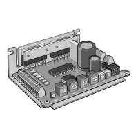
Describes the product as open frame microstepping drivers.

Safety Precautions and Symbols

Explains safety signs, graphic symbols, warnings, and cautions for safe operation.

Additional Usage Precautions

Regeneration Hazards

Explains potential damage from regeneration energy and how to avoid it.

General Specifications and Environment

Details operating environment conditions and general specifications.

Regulations and Product Verification

Covers regulatory compliance, product checking, and component identification.

Product Installation Guide

Installation Method Options

Details mounting methods and precautions for installing the driver.

Installation Location Requirements

Specifies environmental and physical conditions for proper installation.

Installation Orientation and Spacing

Guides on mounting orientation, clearances, and hardware for vertical/horizontal installation.

Electrical Connection Guide

Connection Example (5 VDC)

Illustrates typical wiring for signal voltage at 5 VDC, including I/O signals.

Connection Example (24 VDC)

Illustrates typical wiring for signal voltage at 24 VDC, including I/O signals.

Motor Connection Details

Explains how to connect the motor, including pin assignments and wire colors for different models.

Configuration and Noise Control

Connector Pin Assignments Overview

Details pin assignments for power supply, I/O signals, and motor connectors.

Power Supply Connection

Guides on selecting and connecting the DC power supply, with current capacity requirements.

Electrical Noise Measures

Provides methods to prevent and suppress electrical noise affecting the driver.

Grounding and Static Electricity Precautions

Grounding Methods

Details effective grounding techniques for electrical noise reduction and safety.

Static Electricity Handling

Advises on precautions to prevent damage from static electricity.

Input Signal Operations

Pulse Input Modes (1-pulse & 2-pulse)

Explains how to set and use 1-pulse and 2-pulse input modes for motor control.

AWO (All Windings Off) Input

Describes the function of the AWO input for disabling motor holding torque.

CS (Step Angle Switching) Input

Explains how to switch motor step angles using the CS input.

ACDOFF (Auto Current Down Release) Input

Details the ACDOFF input function for reducing motor current at standstill.

Output Signals and Timing

Output Signals

Describes the driver's photocoupler/open-collector output signals.

TIM (Timing) Output

Explains the TIM output signal for detecting motor shaft rotation and its applications.

Setting Motor Operation

Pulse Input Mode Setting

How to select between 1-pulse and 2-pulse input modes using SW-1.

Step Angle Setting

How to set motor step angles using SW-2, SW-3, and SW-4 switches.

Motor Current Settings

Setting Motor Operation Current

How to set the motor operating current using the RUN switch.

Setting Motor Standstill Current

How to adjust the motor standstill current using the STOP potentiometer.

Troubleshooting and Inspection

Inspection Checklist

Recommended periodic inspections for the driver and connection parts.

Troubleshooting Common Issues

Provides possible causes and remedial actions for motor operation problems.

Accessories and Support

Available Accessories

Lists optional accessories like connection cables, pulse converters, and CR circuits.

Contact Information

Provides contact details for Oriental Motor offices worldwide for further assistance.

Overview

Oriental Motor CMD Driver Operating Manual

This document provides a comprehensive overview of the Oriental Motor CMD Driver, an open-frame microstepping driver designed for unipolar-connection stepping motors. It covers essential aspects from installation and connection to operation, troubleshooting, and maintenance.

General Description

The CMD Driver is a compact, open-frame microstepping driver for 2-phase stepping motors. It is designed for integration into general industrial equipment and offers precise control over stepping motors through various input signals and adjustable settings. The driver operates on a 24 VDC power supply and is capable of driving a range of Oriental Motor stepping motors, with specific combinations detailed in the manual.

Important Technical Specifications

Power Supply:

  • Input Voltage: 24 VDC ±10%
  • Power Supply Current Capacity:
    • CMD2109P: 1.5 A or more
    • CMD2112P: 1.7 A or more
    • CMD2120P: 2.9 A or more
  • DC power supply with reinforced insulation on its primary and secondary sides is required.

Operating Environment:

  • Ambient Temperature: 0 to +40 °C (+32 to +104 °F) (non-freezing)
  • Humidity: 85% or less (non-condensing)
  • Altitude: Up to 1,000 m (3,300 ft.) above sea level
  • Atmosphere: No corrosive gas, dust, water, or oil.
  • Installation: Inside an enclosure, in a well-ventilated location, free from direct sun, excessive dust, splashing water, salt, continuous vibration, excessive shocks, electromagnetic noise, radioactive materials, magnetic fields, or vacuum.

Input Signals:

  • PLS (CW) and DIR (CCW) inputs: 5 VDC input specification. If V0 exceeds 5 V, an external resistor R1 must be connected.
  • AWO (All Windings Off), CS (Step Angle Switching), ACDOFF (Auto Current Down Release) inputs: Can be connected directly to 5 VDC or 24 VDC.
  • Maximum Input Pulse Frequency: 100 kHz (duty cycle 50%).

Output Signals:

  • TIM (Timing) output: Photocoupler/open-collector output (5 to 24 VDC, Output current 10 mA or less).
  • If output signal current exceeds 10 mA, an external resistor R2 must be connected to keep the current to 10 mA or below.

Motor Current Settings:

  • Operating Current (RUN): 16 adjustable levels (e.g., CMD2109P: 0.12 A/phase to 0.95 A/phase; CMD2120P: 0.58 A/phase to 2 A/phase).
  • Standstill Current (STOP): Adjustable via potentiometer, typically 40% of the operating current.

Step Angle Settings:

  • Adjustable via SW-2, SW-3, SW-4 switches to select from 5 step angles (e.g., 1.8°, 0.9°, 0.45°, 0.225°, 0.1125° for a base step angle of 1.8°/step).

Compliance:

  • CE Marking: Conforms to EMC Directive (EN 55011 group 1 class A, EN 61000-6-4; EN 61000-6-2).
  • RoHS Directive (2011/65/EU).
  • Republic of Korea, Radio Waves Act (KC Mark affixed).

Usage Features

Installation:

  • The driver must be installed on a metal plate with excellent vibration resistance, either vertically or horizontally. Vertical installation requires the power element to face up and the aluminum electrolytic capacitor to face down to prevent heat damage.
  • Mounting can be done using either "cutout for mounting A" or "cutout for mounting B," but not both concurrently.
  • Clearances: At least 25 mm (0.98 in.) horizontally and 50 mm (1.97 in.) vertically from the enclosure or other equipment. For side-by-side installations of multiple drivers, provide 20 mm (0.79 in.) horizontally and 50 mm (1.97 in.) vertically.
  • Torque for mounting screws: 0.5 N-m (71 oz-in).

Connection:

  • Motor connection: Specific pin assignments vary by motor model. It is crucial to connect motor lead wires correctly and securely to CN3 to prevent damage.
  • Power supply connection: Connect to CN1, observing polarity.
  • I/O signal connection: Connect to CN2. Cables should be as short as possible to minimize noise effects.
  • Noise measures: Employ noise filters, CR circuits for surge suppression, shielded twisted pair cables, and proper grounding techniques. Keep power lines separate from signal lines.

Operation Modes:

  • Pulse Input Mode: Selectable between 1-pulse input mode (PLS for pulse, DIR for direction) and 2-pulse input mode (CW for clockwise pulse, CCW for counter-clockwise pulse) via SW-1.
  • Motor Operating Current Setting (RUN): Adjustable via a dial switch to match motor requirements and reduce vibration/temperature.
  • Motor Standstill Current Setting (STOP): Adjustable via a potentiometer to reduce heat generation when the motor is stopped. The standstill current is a percentage of the operating current.
  • Step Angle Switching (CS input): Allows dynamic switching between basic and set step angles. Changing CS input during operation may cause loss of synchronism.
  • All Windings Off (AWO input): When ON, cuts off motor current, allowing manual rotation of the output shaft.
  • Auto Current Down Release (ACDOFF input): When OFF, automatically reduces motor current to standstill current after pulse output stops, suppressing heat generation.

Timing Output (TIM):

  • Outputs a signal every time the motor output shaft rotates by a specific angle (e.g., 7.2° for standard type motors). Useful for detecting home positions in conjunction with other sensors.

Maintenance Features

Periodic Inspection:

  • Regularly check for loose mounting screws or connection parts.
  • Inspect for dust accumulation on the driver.
  • Monitor for strange smells or appearances within the driver, which could indicate abnormal conditions.

Troubleshooting:

  • The manual provides a detailed troubleshooting guide for common issues such as unstable motor operation, loss of synchronization, motor not moving, current not dropping, excessive motor vibration, motor overheating, and TIM output malfunction.
  • Remedial actions include checking connections, adjusting settings (current, step angle, acceleration/deceleration time), implementing noise countermeasures, and ensuring proper load conditions.

Safety Precautions:

  • Only qualified personnel should install, wire, operate, inspect, and troubleshoot the product.
  • Always turn off the driver power before connecting/unplugging connectors or when an abnormal condition occurs.
  • Avoid touching the product during or immediately after operation to prevent burns.
  • Do not disassemble or modify the product.
  • Ensure the power supply voltage is within the specified range.
  • Provide an emergency stop device for the entire equipment.
  • Handle the driver with care, especially regarding static electricity, as it uses sensitive semiconductor elements.

Accessories:

  • Connection cable set (LCS01CMK2): Includes cables for power supply, I/O signals, and motor connection.
  • Connection cable (for signal) (CC12Dxxx-2 series): Shielded twisted pair cables for I/O signals, available in various lengths.
  • Pulse signal converter for noise immunity (VCS06): Eliminates pulse signal noise and converts to line driver type.
  • CR circuit for surge suppression (EPCR1201-2, VCS02): Protects relay or switch contacts from surges.

Oriental motor CMD Specifications

General IconGeneral
BrandOriental motor
ModelCMD
CategoryDC Drives
LanguageEnglish

Related product manuals