8
z
PLS (CW) input, DIR (CCW) input
Set a desired pulse input mode of the driver according to the pulse output
mode of the controller used with the driver.
Maximum input pulse frequency: 100 kHz (duty cycle is 50%)
The interval for when the rotation direction is switched represents the
response time of the driver. Set it to the time required for the motor to
respond to the applicable pulse input.
•
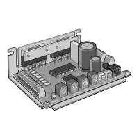
1-pulse input mode
When the PLS input is turned from ON to OFF while the DIR input is ON, the
motor will rotate by one step in CW direction.
When the PLS input is turned from ON to OFF while the DIR input is OFF, the
motor will rotate by one step in CCW direction.
Input pulse signals having pulse waveforms with sharp rising and falling
edges, as shown in the gure.
CWCCW
90%
10%
5 µs or more5 µs or more
2 µs or less2 µs or less
ON
OFF
ON
10 µs or more 10 µs or more
OFF: 0 to 1 V
When the motor is at standstill, be sure to keep the photocoupler in
OFF state.
•
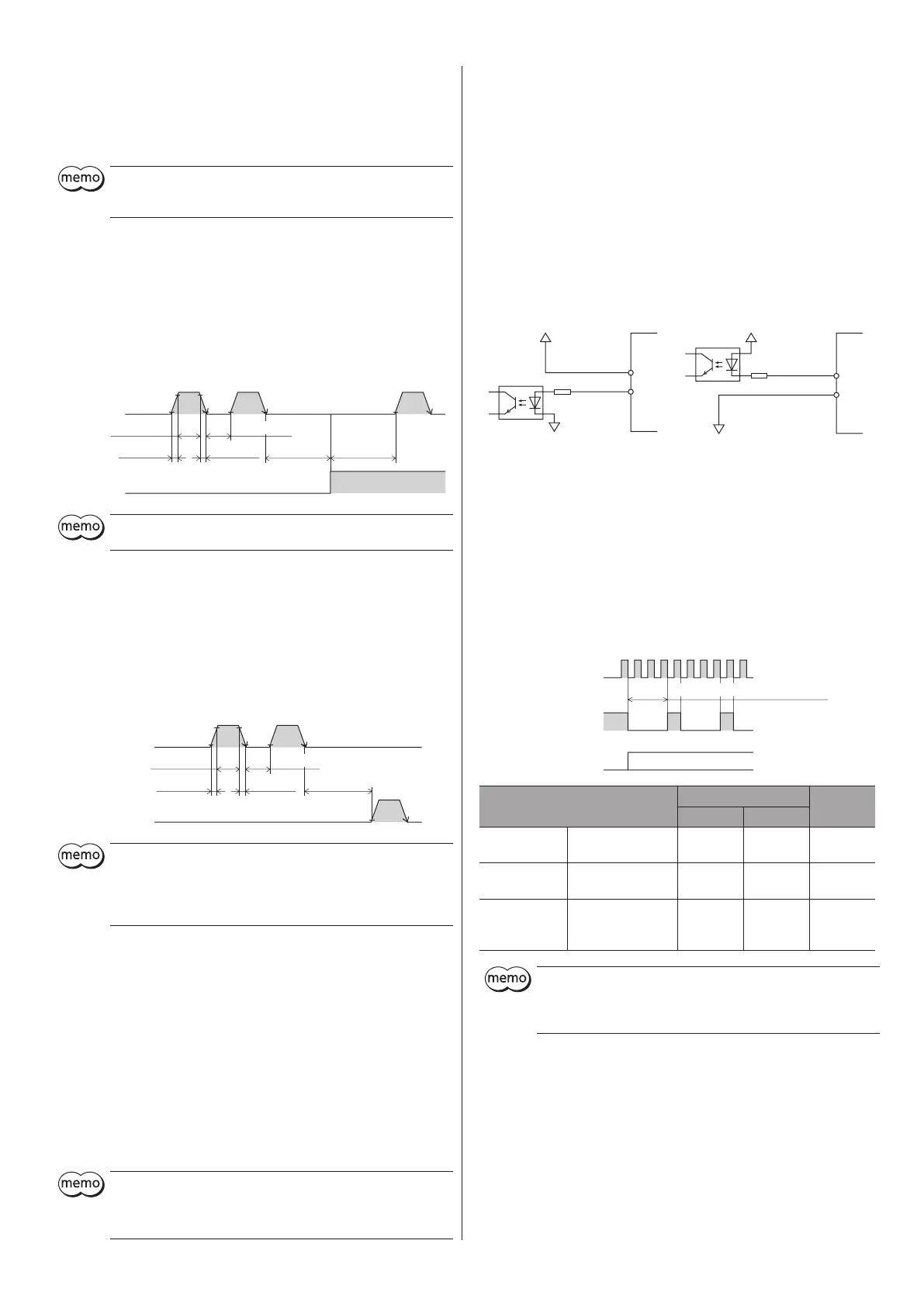
2-pulse input mode
When the CW input is turned from ON to OFF, the motor will rotate by one
step in CW direction.
When the CCW input is turned from ON to OFF, the motor will rotate by one
step in CCW direction.
Input pulse signals having pulse waveforms with sharp rising and falling
edges, as shown in the gure.
90%
10%
5 µs or more5 µs or more
2 µs or less2 µs or less
W input
ON
OFF
ON
CW input
10 µs or more
OFF: 0 to 1 V
y
When the motor is at standstill, be sure to keep the photocoupler in
OFF state.
y
Do not input the CW pulse and CCW pulse simultaneously. If the
other pulse is input while one of the pulse is ON, the motor cannot
operate normally.
z
AWO (all windings o) input
[ON: 4.5 to 26.4 V, OFF: 0 to 1 V]
When the AWO input is turned ON, the motor current will be cut o and the
motor will lose its holding torque. The motor output shaft can be turned
manually.
When the AWO input is turned OFF, current will be supplied and the holding
torque will be restored.
z
CS (step angle switching) input
[ON: 4.5 to 26.4 V, OFF: 0 to 1 V]
When the CS input is turned ON, the motor rotates at a basic step angle.
When the CS input is turned OFF, the motor rotates at the step angle set by
the driver
step angle setting switches (SW-2, SW-3, SW-4)
.
y
Do not change the CS input while operating. The motor may lose its
synchronism, causing position deviation or standstill of the motor.
y
When changing the step angle using the CS input, do so while the
TIM output is ON.
z
ACDOFF (auto current down release) input
[ON: 4.5 to 26.4 V, OFF: 0 to 1 V]
When the ACDOFF input is turned OFF, the motor current will automatically
drop to the standstill current in approximately 0.1 second after the stopping
of pulse output. This mechanism suppresses heat generation from the motor
or driver while the motor is at standstill.
Keep the ACDOFF input OFF in normal conditions of use.
Output signals
The driver outputs signals are photocoupler/open-collector output. The signal
output state represents "ON: Carrying current" or "OFF: Not carrying current"
state of the internal photocoupler.
•
Example of connection with
a current sink input circuit
11
12
•
Example of connection with
a current source input circuit
11
12
z
TIM (timing) output
Every time the motor output shaft rotates by 7.2° (3.6° for high-resolution
type), the motor excitation state becomes the initial setting state (step 0), and
the TIM output turns ON. If an AND circuit is congured with signals of the
home sensor and TIM output when the home position in the equipment is
detected, the tolerance for the motor stop positions in a detection range of
the home sensor can be reduced and the further accurate home position can
be detected.
Example of output signal for standard type motor
When the base step angle is 1.8° (resolution 200 P/R)
ulse input
ON
OFF
ON
OFF
Motor operation
Motor output shaf
Motor type
Number of divisions
TIM output
1 4
Standard
Base step angle
1.8°/step
1.8° 0.45° Every 7.2°
High-resolution
Base step angle
0.9°/step
0.9° 0.225° Every 3.6°
Geared
Base step angle
0.1°/step
(Gear ratio 18)
0.1° 0.025° Every 0.4°
y
When using the TIM output, set the pulse or step angle so that the
motor output shaft stops at an integral multiple of 7.2°.
y
When changing the step angle, do so while the TIM output is ON
and the motor is at standstill.
 Loading...