7
y
Grounding multiple points will increase eect to block electrical noise
because impedance on the grounding points is decreased. However,
ground them so that a potential dierence does not occur among the
grounding points. A connection cable (for signal) that includes a ground
wire is provided. Refer to p.12 for details.
y
To ground a shielded cable, use a metal cable clamp that will maintain
contact with the entire circumference of the cable. Ground the cable clamp
near the product.
Cable clamp
Shielded cable
•
Suppression of eect by noise propagation
y
Loop the noise propagated cable around a ferrite core. Doing so will
prevent the propagated noise invades into the driver or emits from the
driver. The frequency band in which an eect by the ferrite core can be
seen is generally 1 MHz or more. Check the frequency characteristics of the
ferrite core used. To increase the eect of noise attenuation by the ferrite
core, loop the cable a lot.
y
Use the line driver type, which is less likely to be aected by electrical noise,
for the output circuit of pulse signals. If the pulse signal of the controller is
of the open collector type, use a pulse signal converter for noise immunity.
Refer to p.12 for details.
z
Noise suppression parts (accessories)
Refer to p.12 for accessory.
•
Connection cable (for signal)
This cable is a shielded twisted pair cable for good noise immunity to connect
the driver and controller. The ground wires useful to grounding are provided
at both ends of the cable. The EMC measures are conducted using the
Oriental Motor connection cable (for signal).
•
Pulse signal converter for noise immunity
This is a noise lter for pulse signal lines. It eliminates the noise of the pulse
signal, and converts the pulse signal to the line driver type.
•
Surge suppressor
This product is eective to suppress the surge which occurs in a relay contact
part. Connect it when using a relay or electromagnetic switch. CR circuit for
surge suppression and CR circuit module are provided.
Conformity to the EMC Directive
Eective measures must be taken against the EMI that the motor and driver
may give to adjacent control-system equipment, as well as the EMS of the
motor and driver itself, in order to prevent a serious functional impediment in
the machinery. The use of the following installation and wiring methods will
enable the motor and driver to be compliant with the EMC Directive. Refer to
p.2 for the applicable standards.
Oriental Motor conducts EMC measurements on its motors and drivers in
accordance with the "Example of motor and driver installation and wiring"
shown later.
The user is responsible for ensuring the machine's compliance with the EMC
Directive, based on the installation and wiring explained below.
•
Power supply
The
CMD
Driver is a product of DC power input. Use a DC power supply
(switched-mode power supply etc.) that conforms to the EMC Directive.
•
Connecting the signal cable
Refer to "Prevention of noise propagation" p.6.
•
How to ground
y
The cable used to ground the motor, driver and noise lter must be as thick
and short as possible so that no potential dierence is generated.
y
Choose a large, thick and uniformly conductive surface for the grounding
point.
y
Install the motor to the grounded metal plate.
•
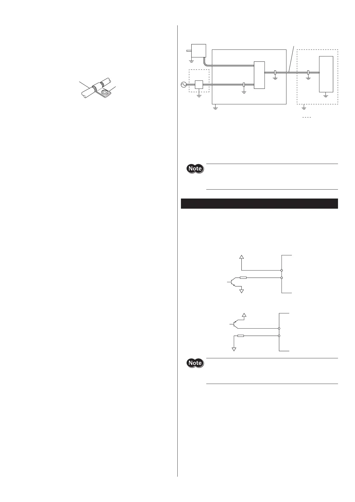
Example of motor and driver installation and wiring
Motor
Driver
DC power
supply
Cable
clamp
Cable
clamp
Grounded panel
Cable for motor
Controller
Power supply
cable
(connection cable)
Cable
clamp
Grounding
Grounding
Grounding
Grounding
Grounding Grounding
Grounding
Grounding
•
Precautions about static electricity
Static electricity may cause the driver to malfunction or suer damage. While
the driver is receiving power, handle the driver with care and do not come
near or touch the driver.
Always use an insulated screwdriver to adjust the driver's switches.
The driver uses parts that are sensitive to electrostatic charge. Before
touching the driver, turn o the power to prevent electrostatic charge
from generating. If an electrostatic charge is impressed on the driver,
the driver may be damaged.
Explanation of I/O signals
Input signals
The signal input state represents "ON: Carrying current" or "OFF: Not carrying
current" state of the internal photocoupler.
•
Example of connection with a current sink output circuit
1, 3, 5, 7, 9
2, 4, 6, 8, 10
•
Example of connection with a current source output circuit
1, 3, 5, 7, 9
2, 4, 6, 8, 10
The PLS (CW) input and DIR (CCW) input are of the 5 VDC input
specication. If V0 exceeds 5 V, connect an external resistor. The AWO
input, CS input and ACDOFF input can be connected directly to 5 VDC
or 24 VDC.
 Loading...