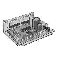
6
Connector pin assignments
CN2
121110 12
+
-
3 4 65
CN3CN1
z
CN1 (power supply)
Pin No. Direction Signal name Description
+
IN POWER
+24 VDC
− GND
z
CN2 (I/O signals)
Pin No. Direction Signal name Description
1
IN
PLS (CW)
+
Pulse (CW pulse) input *
2 −
3
DIR (CCW)
+
Rotation direction
(CCW pulse) input *
4 −
5
AWO
+
All windings o input
6 −
7
CS
+
Step angle switching
input
8 −
9
ACDOFF
+
Auto current down release
input
10 −
11
OUT TIM
+
Timing output
12 −
* When the 1-pulse input mode is set, the signals are the pulse input (PLS) and the
rotation direction input (DIR). When the 2-pulse input mode is set, the signals are
the CW pulse input (CW) and the CCW pulse input (CCW).
z
CN3 (motor)
Pin No. Direction Signal name Description
1
OUT MOTOR
Blue motor lead
2 White motor lead
3 Red motor lead
4 Black motor lead
5 Yellow motor lead
6 Green motor lead
Connector pin assignments vary depending on the motor. For details,
refer to "Connecting the motor" p.5.
Applicable connector
Type Application Model
Connector housing
For power supply (CN1) 51103-0200 (Molex)
For I/O signals (CN2) 51103-1200 (Molex)
For motor (CN3) 51103-0600 (Molex)
Contact − 50351-8100 (Molex)
Applicable crimping tool − 63811-8100 (Molex)
y
For the power supply cable, use a cable of AWG22 (0.3 mm
2
).
y
For the I/O signals cable, use a twisted pair cable of AWG24 to 22 (0.2 to
0.3 mm
2
).
y
Keep the wiring distance as short as possible [less than 2 m (6.6 ft.)] to
suppress the eect of noise.
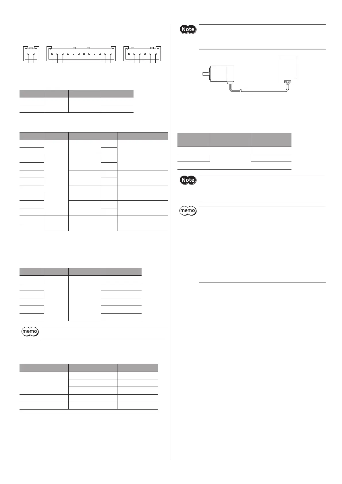
For the motor of the frame size 20 mm (0.79 in.) [
PKP213
,
PKP214
type], since the wire diameter of the motor cable is AWG26, it is too
thin to t in the included connector for motor. Provide the AWG24
(0.2 mm
2
) or thicker cable yourself, and connect by using it.
PKP213
PKP214
Driver
Connecting the power supply
Use a power supply that can supply the following current capacity.
When the power is turned on, the POWER LED will be lit in green.
Driver model
Input power supply
voltage
Power supply
current capacity
CMD2109P
+24 VDC±10%
1.5 A or more
CMD2112P
1.7 A or more
CMD2120P
2.9 A or more
y
When connecting, pay attention to the polarity of the power supply.
Reverse-polarity connection may cause damage to the driver.
y
Have the connector plugged in securely. Insecure connection may
cause malfunction or damage to the driver.
y
When unplugging the connector, do so while spreading the latches
on the connector a little.
y
When cycling the power or plugging/unplugging the connector,
turn o the power and wait for minimum 5 seconds before doing so.
y
Separate I/O cable at least 100 mm (3.94 in.) from electromagnetic
relays and other than inductance loads. Additionally, route I/O cable
perpendicular to power supply cable and motor cable, rather than
in a parallel fashion.
y
Do not wire the power supply cable in the same cable duct with
other power lines or motor cables.
y
If the motor cable or power supply cable generates an undesirable
amount of noise depending on the wiring or conguration, shield
the cable or install a ferrite core.
Noise measures
The electrical noise is of two types: One is a noise to invade into the driver
from the outside and cause the driver malfunction, and the other is a noise to
emit from the driver and cause peripheral equipments malfunction.
For the noise that is invaded from the outside, take measures to prevent the
driver malfunction. It is needed to take adequate measures because signal
lines are very likely to be aected by the noise.
For the noise that is emitted from the driver, take measures to suppress it.
z
Measures against electrical noise
There are the following three methods mainly to take measures against the
electrical noise.
•
Noise suppression
y
When relays or electromagnetic switches are used together with the
system, use noise lters and CR circuits to suppress surges generated by
them.
y
Cover the driver by a metal plate such as aluminum. This is eective in
shielding the electrical noise emitted from the driver.
•
Prevention of noise propagation
y
Place the power lines, such as the motor and power supply cables, keeping
a distance of 100 mm (3.94 in.) or more from the signal lines, and also do
not bundle them or wire them in parallel. If the power cables and signal
cables have to cross, cross them at a right angle.
y
Use shielded twisted pair cables of AWG22 (0.3 mm
2
) or thicker for power
lines and AWG24 (0.2 mm
2
) or thicker for signal lines.
y
Keep cables as short as possible without coiling and bundling extra lengths.
 Loading...