5
z
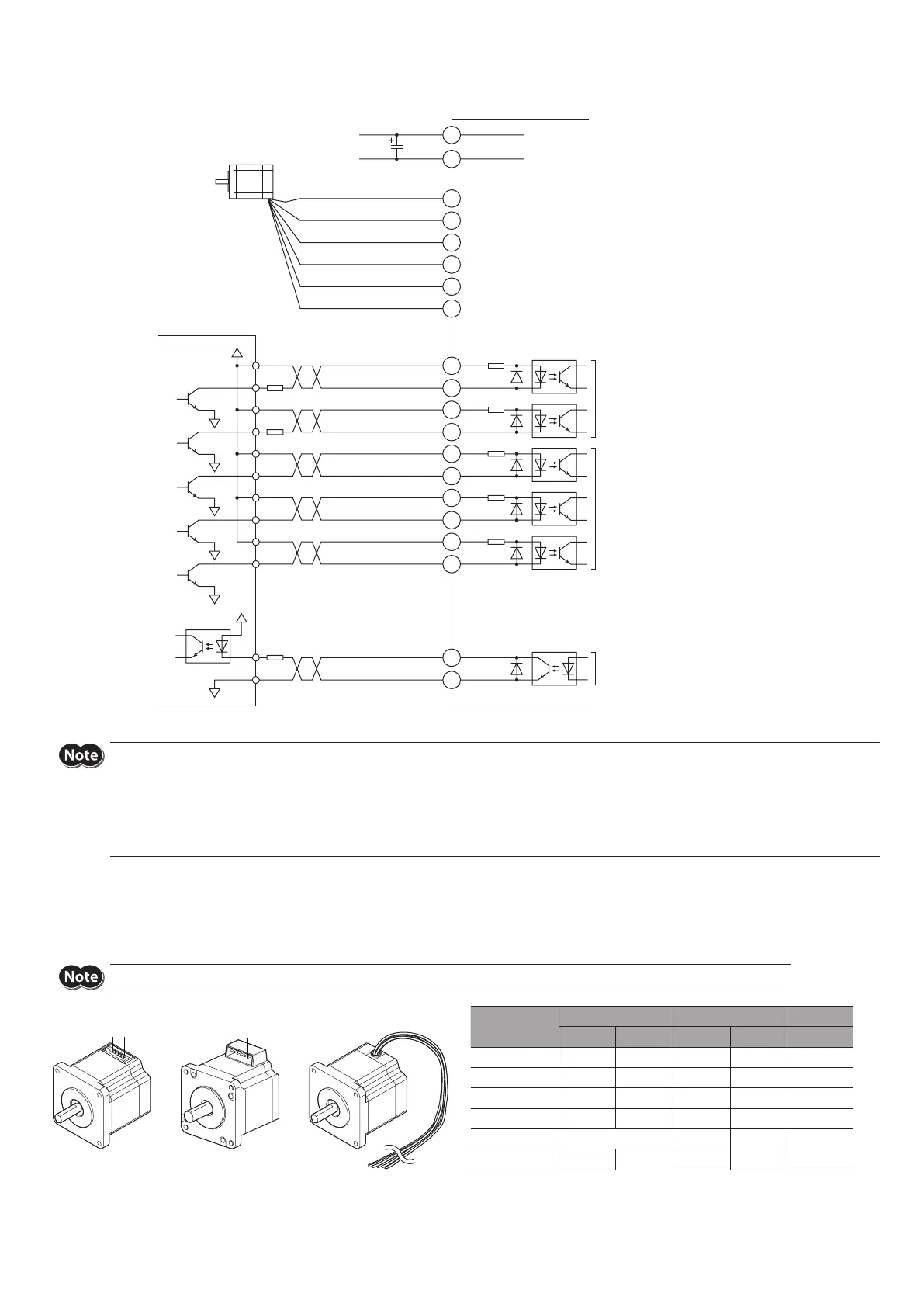
When using the voltage of input signals at 24 VDC
Blue
Red
White
Green
Yellow
Black
V0 (24 VDC)
V0 (24 VDC)
GND
24 VDC±10%
Motor lead wire *
Controller
Photocoupler input
5 to 24 VDC
Input current 5 to 20 mA
Photocoupler input
24 VDC
Input current 8 mA
Photocoupler/open-collector output
5 to 24 VDC
Output current 10 mA or less
R2
R1
R1
200 Ω
200 Ω
3.3 kΩ
3.3 kΩ
3.3 kΩ
DIR
-
(CCW
-
)
PLS
-
(CW
-
)
PLS+ (CW+)
DIR+ (CCW+)
AWO
-
AWO+
CS
-
CS+
TIM
-
TIM+
ACDOFF
-
ACDOFF+
CN1
CN3
CN2
1
2
+
1
2
3
4
6
5
-
3
4
5
6
7
8
9
10
11
12
0 V
0 V
0 V
0 V
0 V
0 V
C
Twisted pair cable
* Connector pin assignments vary depending on the motor. For details, refer to the following "Connecting the motor."
y
The PLS (CW) and DIR (CCW) inputs are of the 5 VDC input specication. If V0 exceeds 5 V, connect external resistor R1.
Example) When V0 is 24 VDC R1: 1.5 to 2.2 kΩ, 0.5 W or more.
y
If the output signal current exceeds 10 mA, connect external resistor R2 to keep the current to 10 mA or below.
y
Driving a large inertia at high speed will generate regenerated energy. This regenerated energy raises the power supply voltage, causing damage to the
driver. If such operation is performed, review the operating condition so that the temporary rise of the power supply voltage by the regenerated energy is
8 V or less, or connect an electrolytic capacitor C in parallel to the power line (A rated voltage of 50 V or more and a capacitance of 10,000 µF or more are
recommended).
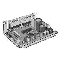
Connecting the motor
Connector pin assignments vary depending on the motor. Refer to the table.
The pin number is shown in the gure.
“Color” in the table represents the color of the lead wire for the connection cable (included or accessory).
The motors of the model A and model B are dierent in pin assignments. Wrong connection will not cause the motor to operate properly.
51
6
Pin No. →
1
Driver
CN3 Pin No.
Model A Model B Model C
Pin No. Color Pin No. Color Color
1 4 Blue 1 Blue Blue
2 3 White 2 White White
3 5 Red 3 Red Red
4 1 Black 4 Black Black
5 − 5 Yellow Yellow
6 2 Green 6 Green Green