4
Connection
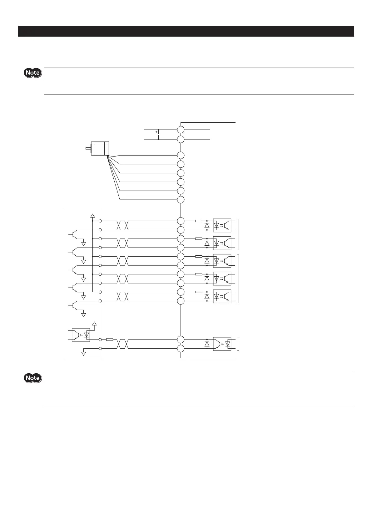
Connection example
Either 5 or 24 VDC can be used as the signal voltage for the AWO input, CS input and ACDOFF input.
y
Check the colors of motor lead wires and connect them correctly and securely. Wrong connection of lead wires or poor contact may cause damage to the
driver.
y
Be sure to wire the I/O signals cable connecting the driver and controller as short as possible. The maximum input frequency will decrease as the cable length
increases.
z
When using the voltage of input signals at 5 VDC
Blue
Red
White
Green
Yellow
Black
V0 (5 VDC)
V0 (5 VDC)
GND
24 VDC±10%
Motor lead wire *
Controller
Photocoupler input
5 VDC
Input current 5 to 20 mA
Photocoupler input
5 VDC
Input current 1 mA
Photocoupler/open-collector output
5 to 24 VDC
Output current 10 mA or less
R2
200 Ω
200 Ω
3.3 kΩ
3.3 kΩ
3.3 kΩ
DIR
-
(CCW
-
)
PLS
-
(CW
-
)
PLS+ (CW+)
DIR+ (CCW+)
AWO
-
AWO+
CS
-
CS+
TIM
-
TIM+
ACDOFF
-
ACDOFF+
CN1
CN3
CN2
1
2
+
1
2
3
4
6
5
-
3
4
5
6
7
8
9
10
11
12
0 V
0 V
0 V
0 V
0 V
0 V
C
Twisted pair cable
* Connector pin assignments vary depending on the motor. For details, refer to "Connecting the motor" p.5.
y
If the output signal current exceeds 10 mA, connect external resistor R2 to keep the current to 10 mA or below.
y
Driving a large inertia at high speed will generate regenerated energy. This regenerated energy raises the power supply voltage, causing damage to the
driver. If such operation is performed, review the operating condition so that the temporary rise of the power supply voltage by the regenerated energy is
8 V or less, or connect an electrolytic capacitor C in parallel to the power line (A rated voltage of 50 V or more and a capacitance of 10,000 µF or more are
recommended).